Exposure apparatus and image forming apparatus

a technology of image forming apparatus and image forming apparatus, which is applied in the direction of electrographic process apparatus, printing, instruments, etc., can solve the problems of difficult to obtain the light (luminance) required for exposure, difficult to arrange several thousands of light-emitting points with high precision, and the driver for driving each el element cannot be internally mounted on the substrate, etc., to achieve convenient and excellent performance, sufficient degree of gray-scale levels, and the effect of freedom in the structure of the imag

Inactive Publication Date: 2006-07-06
SEIKO EPSON CORP
View PDF4 Cites 5 Cited by
  • Summary
  • Abstract
  • Description
  • Claims
  • Application Information

AI Technical Summary

Benefits of technology

[0009] An advantage of some aspects of the invention is that it provides an exposure apparatus in which gray-scale level can be easily displayed, a driving element for internal mounting can be used as a driver, the light amount necessary for exposure can be obtained and the lifespan of each line is almost the same, and an image forming apparatus including the exposure apparatus.

Problems solved by technology

However, it is very difficult to arrange several thousands of light-emitting points with high precision.
In the line head using the organic EL element as the light-emitting element, it is very difficult to obtain the sufficient amount of light (luminance) required for exposure.
As a result, a driver for driving each EL element cannot be internally mounted on the substrate.
Therefore, the degree of freedom not only in manufacturing the line head (printer head), but also in terms of the structure of an exposure apparatus or an image forming apparatus including such external mounting driver is limited.
Furthermore, each of the EL elements can obtain a necessary light amount since a plurality of EL elements performs exposure on the same unit drawing region although one EL element cannot obtain sufficient luminance (light amount).

Method used


Image

  • Exposure apparatus and image forming apparatus
  • Exposure apparatus and image forming apparatus
  • Exposure apparatus and image forming apparatus

Examples


embodiments

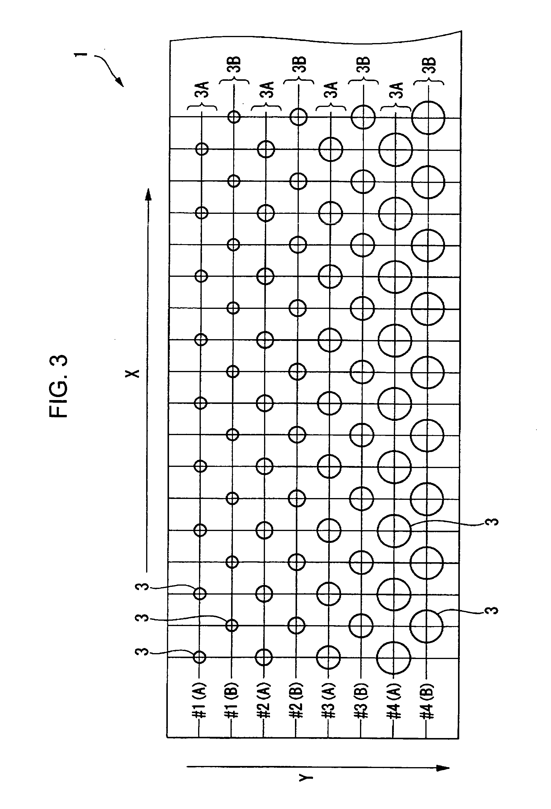
[0124] Embodiments of the exposure apparatus having the line head 1 shown in FIG. 3 will be described below.

[0125] In the exposure apparatus of the present embodiment, a line image with 600 dots / inch can be drawn (exposed). Both the group A and the group B include the organic EL elements 3 of 300 dots / inch, i.e., 300 organic EL elements 3 / inch in the X-axis direction of FIG. 3. The organic EL elements 3 form each of the organic EL element columns 3A, 3B.

[0126] In addition, exposure is performed by scanning and lighting the four organic EL element columns 3A, 3B, each having the area ratio as describe above, in the order of #1, #2, #3 and #4 along the Y-axis direction of FIG. 3 which is a paper feed direction (a rotational direction of the photosensitive drum 9).

[0127] The sensitivity of a typical photosensitive drum is constructed to obtain the linearity whose exposure amount is up to about 0.2 μJ / cm2. Therefore, the maximum value capable of obtaining the linearity is set to the ...


PUM


Abstract

An exposure apparatus includes a line head in which a plurality of EL elements are aligned and a rotatable photosensitive drum, which is exposed by light from the line head. The line head includes N (where, “N” is 2 or greater) EL element columns in which the alignment direction of the EL elements is parallel to the rotational axis of the photosensitive drum. In each of the EL element columns, the area of a light-emitting pixel of the EL element which emits light is constant within a corresponding column. When the column number of the EL element columns is from 1 to N, the area S of the light-emitting pixel of the EL element in each of the columns is Si=S1×2i−1 (where, “i” is the column number of each of the EL element columns and a natural number from 1 to N, and “S1” is the area of the light-emitting pixel of the EL element of a first column). One or a plurality of EL elements selected from N EL elements within the N EL element columns perform exposure on the same unit drawing region on the photosensitive drum.

Description

BACKGROUND [0001] 1. Technical Field [0002] The present invention relates to an exposure apparatus and to an image forming apparatus including the exposure apparatus. [0003] 2. Related Art [0004] Printers employing an electrophotographic method generally include line printers (an image forming apparatus). The line printers include a charging unit, a line printer head (a line head), a developing device, a transfer device and the like, which are closely disposed on a circumferential surface of a photosensitive drum, i.e., a subject part to be exposed. That is, exposure is performed on the photosensitive drum, which is charged by the charging unit, by selectively emitting light from a light-emitting element provided in the printer head to form an electrostatic latent image. The latent image is then developed using the toner supplied from the developing device. The transfer device transfers the toner image onto the paper. [0005] Inorganic or organic light emitting diodes (LED) of two co...

Claims


Application Information

Patent Timeline
IPC IPC(8): B41J2/435
CPCG03G15/04072G03G15/326G03G15/04063G03G15/043G03G15/04
Inventor KOBAYASHI, HIDEKAZU
Owner SEIKO EPSON CORP
Why Eureka
Try Eureka