
Mixer and converter using same

a technology of mixer and converter, applied in the direction of modulation transference by diodes, waveguide devices, electromagnetic wave demodulation, etc., can solve the problems of space occupation of balun and unsuitability for miniaturization, and achieve the effect of preventing degradation of balun's characteristics

Inactive Publication Date: 2006-06-29
MURATA MFG CO LTD
View PDF10 Cites 1 Cited by
  • Summary
  • Abstract
  • Description
  • Claims
  • Application Information

AI Technical Summary

Benefits of technology

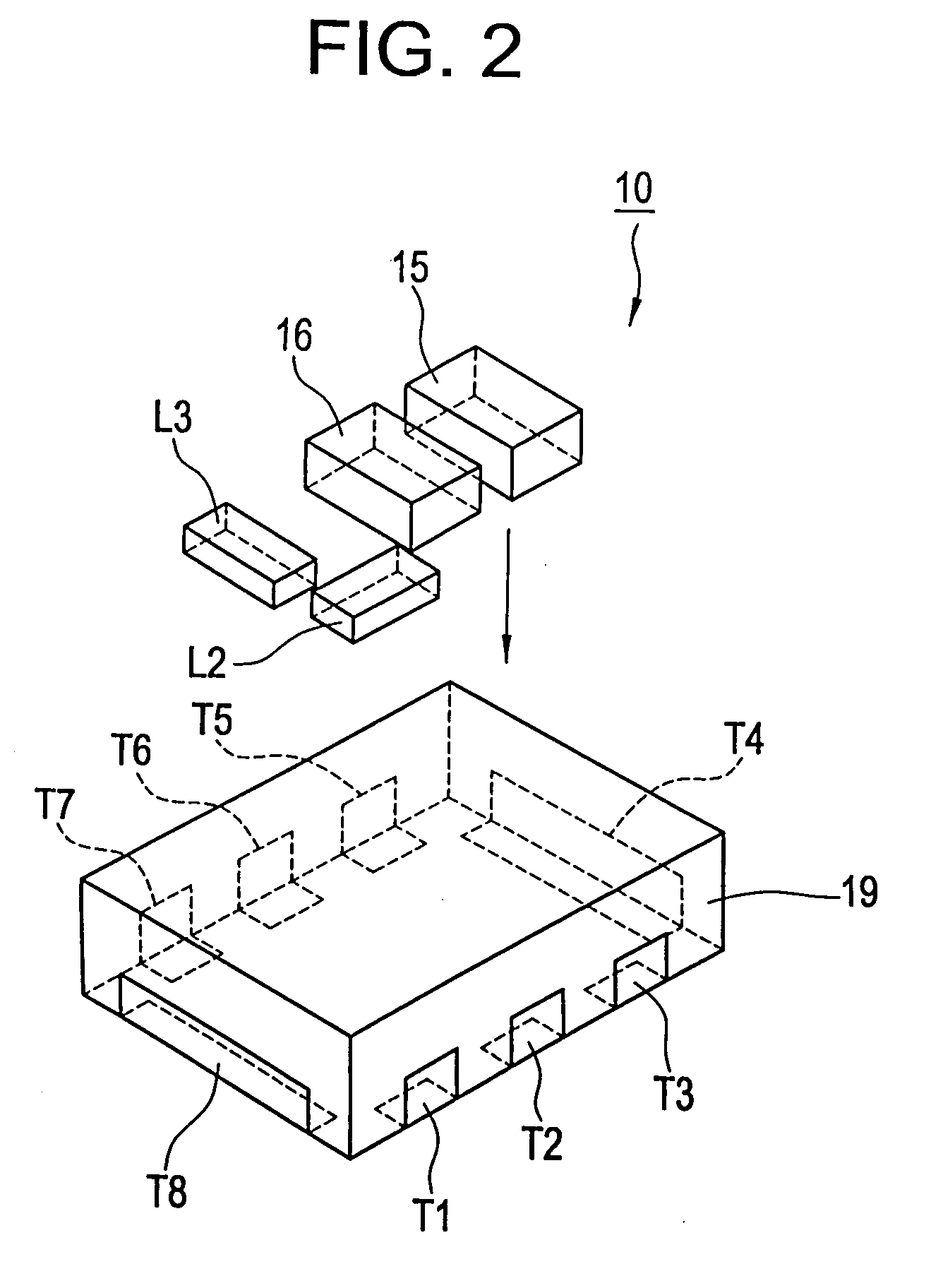
The present invention provides a miniaturized mixer that prevents degradation of its characteristics and a converter including the mixer. The mixer includes a balun with two balanced lines and an unbalanced line, and mixer diodes connected to the balanced terminals, an LO port, an RF port, a high-pass filter, a low-pass filter, and an IF port. The balun, mixer diodes, high-pass filter, and low-pass filter are integrated into a multilayer substrate that includes a plurality of sheet layers that are stacked. The external terminals that function as the LO port, RF port, and IF port are preferably disposed at the side surfaces of the multilayer substrate with external electrodes that function as the ground being provided between them, thus minimizing interference among the external terminals and reducing loss in the mixer. The balanced and unbalanced lines of the balun are provided in the lower section of the multilayer substrate with respect to the stacking direction, which minimizes parasitic inductance in the ground plane and improves phase difference between the balanced lines and the unbalanced line. The capacitor of the low-pass filter is arranged in the upper section of the multilayer substrate with respect to the stacking direction, with the ground electrode being provided between the capacitor and the strip line electrodes that constrain the balanced and unbalanced lines of the balun, which minimizes stray capacitance and improves isolation. The receiving converter described in this patent has a mixer that achieves a significant reduction in loss and can minimize loss in the converter.

Problems solved by technology

According to the mixer 50 of the related art, while it is possible to provide a planarized circuit by forming the balun 54 with microstrip lines, there is a problem in that the balun takes up space and is not suitable for miniaturization because of its shape and size.

Method used


Image

  • Mixer and converter using same
  • Mixer and converter using same
  • Mixer and converter using same

Examples


Embodiment Construction

[0027] Preferred embodiments of the present invention will now be described with reference to the accompanied drawings.

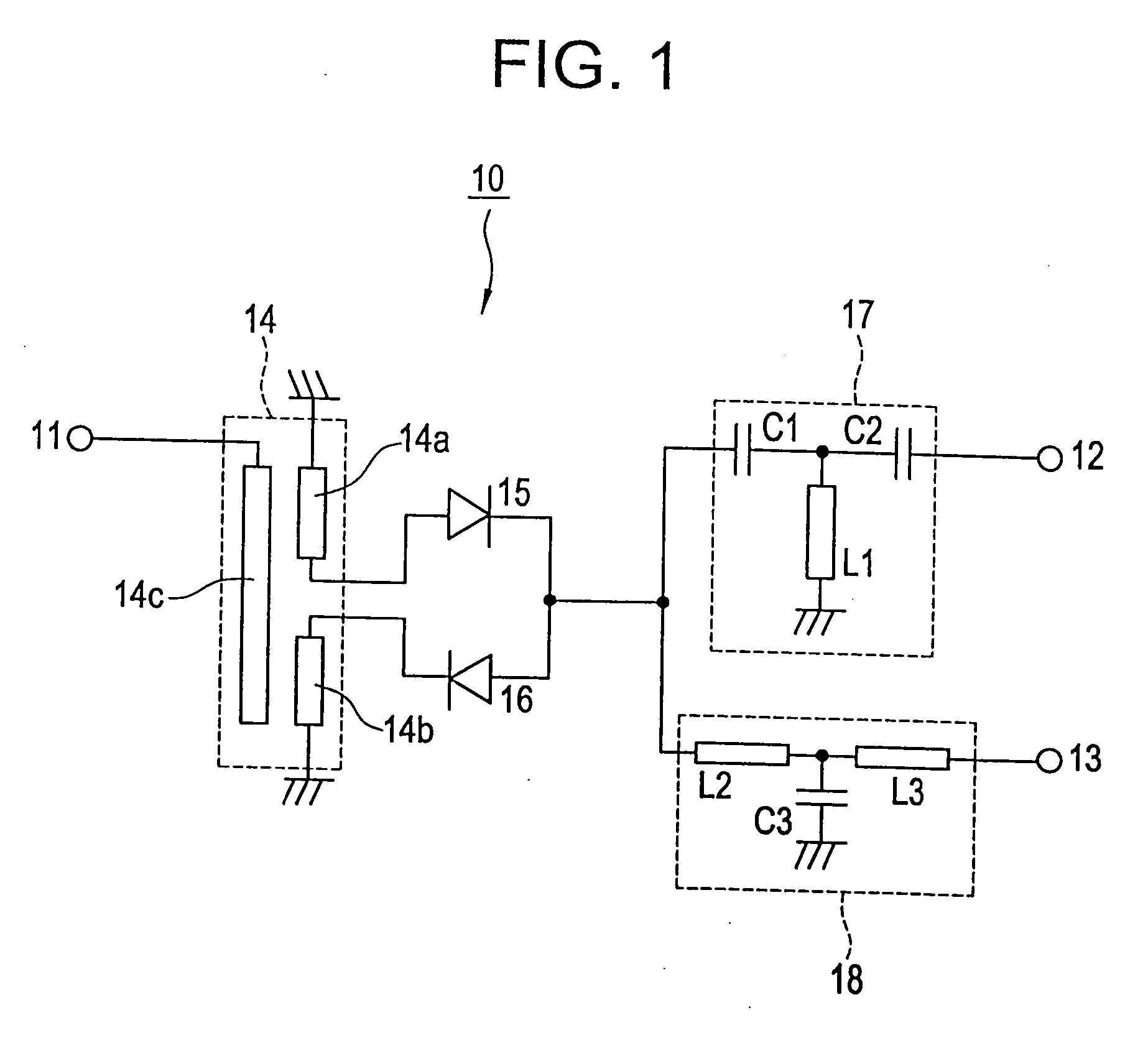
[0028]FIG. 1 is a circuit diagram of a mixer according to a preferred embodiment of the present invention. A mixer 10 is preferably a single balanced mixer, which includes an LO port 11 for inputting an LO signal, an RF port 12 for inputting an RF signal, an IF port 13 for outputting an IF signal, a balun 14 for converting an unbalanced signal into a balanced signal, and a pair of mixer diodes 15 and 16 which are connected in series. The mixer 10 further includes a high-pass filter 17 for blocking LO and IF signals and for passing only an RF signal and a low-pass filter 18 for blocking LO and RF signals and for passing only an IF signal.

[0029] The balun 14 includes balanced lines 14a and 14b and an unbalanced line 14c. The balanced lines 14a and 14b each have a first end that is short-circuited. The second end of the balanced line 14a, which end functions as a bal...


PUM


Abstract

A mixer, which is a single balanced mixer, includes an LO port for inputting an LO signal, an RF port for inputting an RF signal, an IF port for outputting an IF signal, a balun for converting an unbalanced signal into a balanced signal, and a pair of mixer diodes connected in series. The mixer further includes a high-pass filter for blocking LO and IF signals and passing an RF signal and a low-pass filter for blocking LO and RF signals and passing an IF signal.

Description

[0001] This application is a Continuation Application of U.S. patent application Ser. No. 10 / 066,715 filed Feb. 6, 2002, currently pending.BACKGROUND OF THE INVENTION [0002] 1. Field of the Invention [0003] The present invention relates to a mixer and a converter including a mixer. More specifically, the present invention relates to a mixer used for converting frequencies from an RF signal to an IF signal and a converter including such a mixer in a communication apparatus or other apparatus utilizing a microwave band. [0004] 2. Description of the Related Art [0005] In the past, in radio communication apparatuses, a mixer which mixes an RF (radio frequency) signal and an LO (local oscillation) signal has been used to generate an IF (intermediate frequency) signal that is easier to be processed in a circuit at the subsequent stage. As such a mixer, typically, a single balanced mixer or double balanced mixer which can efficiently reduce the leakage of an LO signal toward the output wit...

Claims


Application Information

Patent Timeline
Patent Type & Authority Applications(United States)
IPC IPC(8): H04B1/26H01P5/10H03D7/02H03D9/06
CPCH03D9/0633H01P5/10
Inventor TATSUMI, RYOMATSUMOTO, MITSUHIROBANDO, TOMOYA
Owner MURATA MFG CO LTD
Learn More