
Photoreceptor drums, methods and apparatus for assembling the same, and image-forming apparatus employing the same

a technology of photoreceptor drums and drums, which is applied in the direction of corona discharge, shafts and bearings, instruments, etc., can solve the problems of image printing distortion, positional shifting and color shifting, and uneven distance between the center of rotation the surface of the photoreceptor drum

Active Publication Date: 2006-06-29
MITSUBISHI CHEM CORP
View PDF27 Cites 66 Cited by
  • Summary
  • Abstract
  • Description
  • Claims
  • Application Information

AI Technical Summary

Benefits of technology

[0030] The photoreceptor drums of the invention are exceedingly advantageous for obtaining clear images free from positional image shifting and image blurring.
[0031] According to the assembling methods and apparatus of the invention, a photoreceptor drum capable of giving clear images can be easily obtained without fail.
[0032] According to the image-forming apparatus of the invention, clear images free from positional image shifting and image blurring can be obtained.

Problems solved by technology

Furthermore, when the photoreceptor drum is bent or has axis position shifting, it has unevenness in the distance from the center of rotation of the photoreceptor drum to the surface of the photoreceptor drum, i.e., in radius of rotation.
As a result, the image printed is distorted.
Especially in the case of a color copier of the type called tandem, in which photoreceptor drums arranged in parallel are used, those troubles markedly appear as positional shifting and color shifting because the photoreceptor drums are separately used for respective colors.
In an apparatus employing a light-emitting diode as an illuminator, as another kind of apparatus, rotation with deflection is apt to cause image blurring because of the short focal distance and this problem is serious.
However, it is virtually almost impossible to obtain a photoreceptor drum completely free from deflection.
However, these expedients have come to have limitations with the recent trend toward resolution increase and color image formation in image-forming apparatus.

Method used


Image

  • Photoreceptor drums, methods and apparatus for assembling the same, and image-forming apparatus employing the same
  • Photoreceptor drums, methods and apparatus for assembling the same, and image-forming apparatus employing the same
  • Photoreceptor drums, methods and apparatus for assembling the same, and image-forming apparatus employing the same

Examples


Embodiment Construction

[0038] Embodiments of the photoreceptor drums, methods and apparatus for assembling the same, and image-forming apparatus employing the same according to the invention will be explained below.

[0039] The photoreceptor drums are explained first.

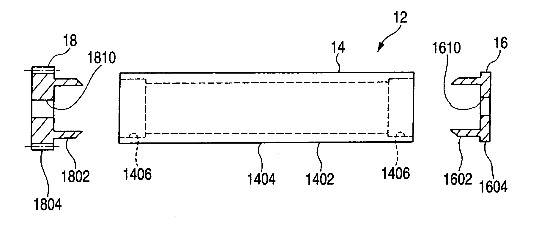
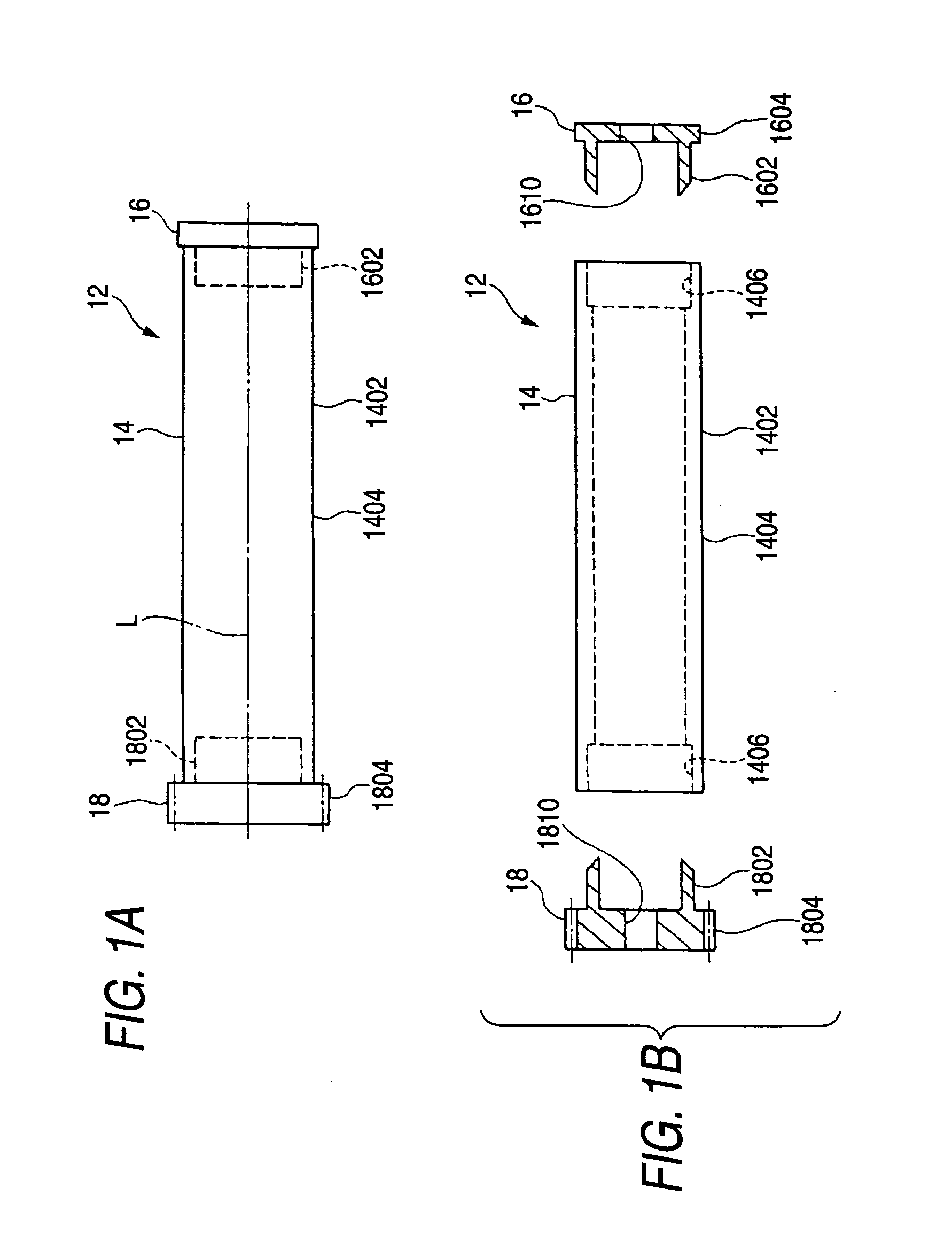
[0040]FIG. 1(A) is a front view of a photoreceptor drum, and (B) is an exploded view of the photoreceptor drum.

[0041] As shown in FIG. 1, the photoreceptor drum 12 is constituted of a drum main body 14 and a first and second flange member 16 and 18 to be concentrically attached to both lengthwise-direction ends of the drum main body 14.

[0042] The drum main body 14 is constituted of a cylindrical body 1402 and a photosensitive layer 1404 formed on the surface of the cylindrical body 1402. The cylindricyal body 1402 has fitting holes 1406 respectively formed in both ends thereof.

[0043] The first flange member 16 is constituted of a cylindrical part 1602 to be fitted into and fixed to the fitting hole 1406 in one end of the drum main body 14,...


PUM


Abstract

An object of the invention is to provide a photoreceptor drum exceedingly advantageous for obtaining clear images free from positional image shifting and image blurring. In the invention, a photoreceptor drum (12) is constituted of a drum main body (14) and a first and second flange member (16) and (18) to be attached respectively to both lengthwise-direction ends of the drum main body (14). The drum main body (14) is constituted of a cylindrical body (1402) and a photosensitive layer (1404) formed on the surface of the cylindrical body (1402), and the cylindrical body (1402) has a fitting hole (1406) formed in each end thereof. The first and second flange members (16) and (18) have cylindrical parts (1602) and (1802) to be fitted into and fixed to the fitting holes (1406) in the drum main body (14), and further have shaft support parts (1610) and (1810). The photoreceptor drum (12) has been formed so that the radial deflection thereof based on a central axis L connecting the centers of the shaft support parts (1610) and (1810) of the first and second flange members (16) and (18) is 15 μm or less.

Description

TECHNICAL FIELD [0001] The present invention relates to photoreceptor drums (or electrophotographic photoreceptor drums) for use in image-forming apparatus such as electrophotographic apparatus (e.g., copiers and printers), methods and an apparatus for assembling the same, and image-forming apparatus employing the photoreceptor drums. BACKGROUND ART [0002] In image-forming apparatus such as electrophotographic apparatus (e.g., copiers and printers), examples of causes of image blurring and the like include working allowances and assembly allowances of various components of the image-forming apparatus, vibration of the image-forming apparatus, and rotation unevenness of photoreceptor drums attributable to gear transmissions. [0003] The present inventor directed attention to a photoreceptor drum itself, which is a major component of an image-forming apparatus, in order to obtain clear images. [0004] Namely, a photoreceptor drum is constituted of a drum main body having a photosensitiv...

Claims


Application Information

Patent Timeline
Patent Type & Authority Applications(United States)
IPC IPC(8): G03G15/00G03G21/00
CPCG03G15/751G03G15/757
Inventor TAGUCHI, SUSUMU
Owner MITSUBISHI CHEM CORP
Learn More