
Thrust roller bearing apparatus

Inactive Publication Date: 2006-06-29
JTEKT CORP
View PDF6 Cites 9 Cited by
  • Summary
  • Abstract
  • Description
  • Claims
  • Application Information

AI Technical Summary

Benefits of technology

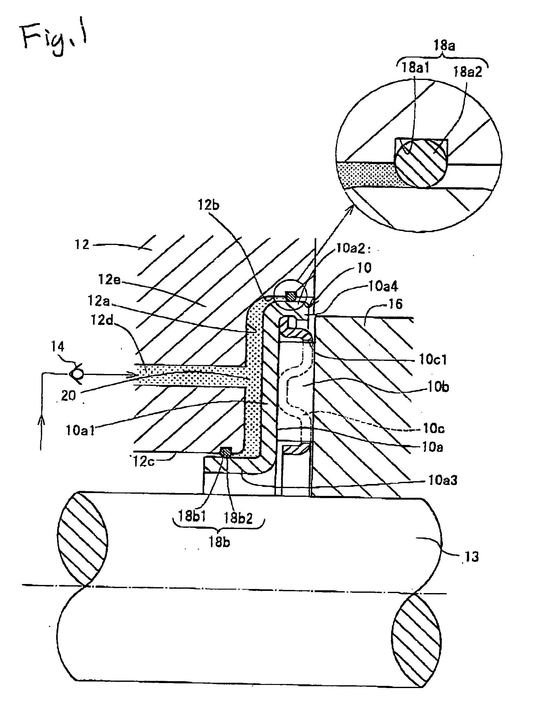
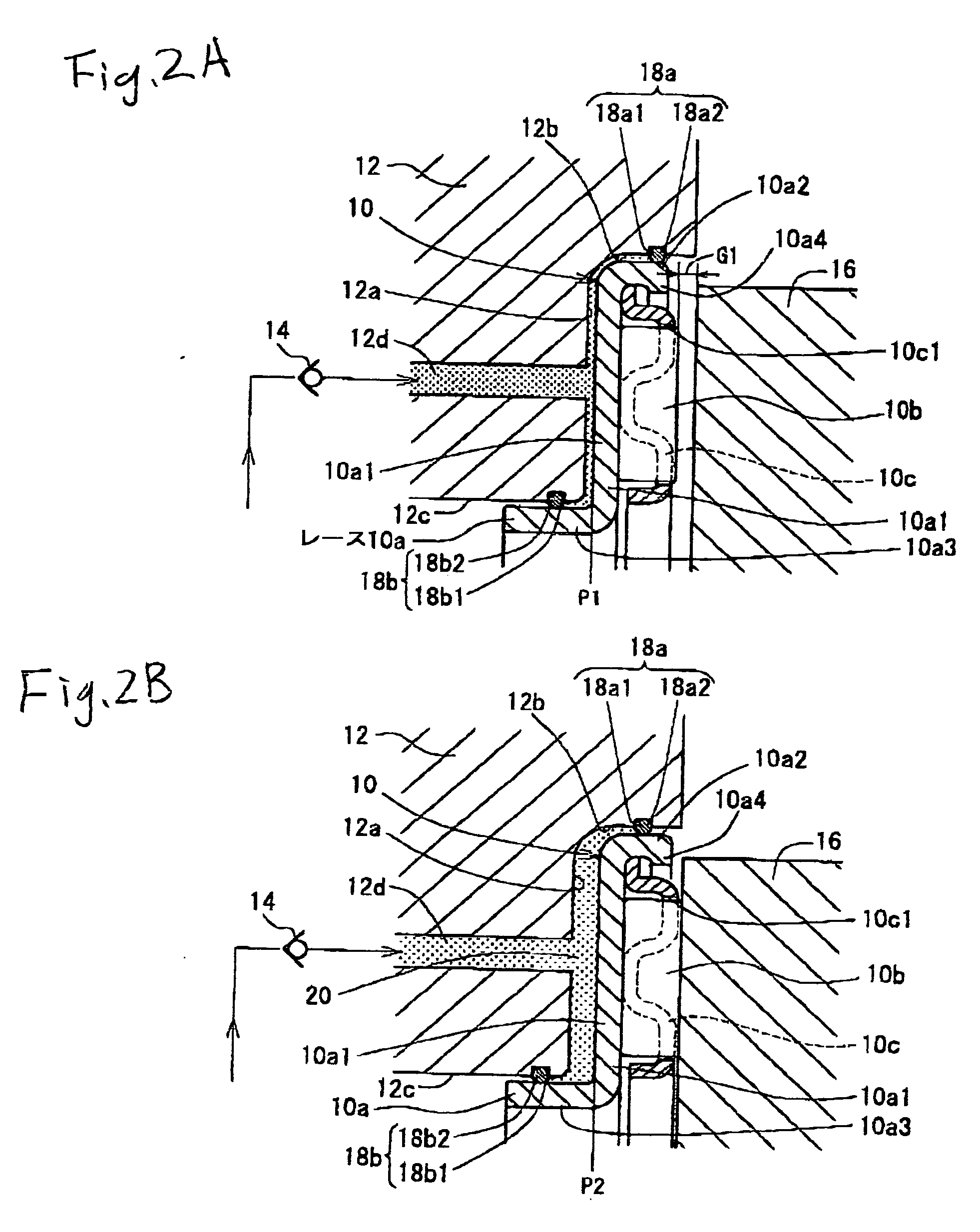
[0006] According to this aspect of the invention, when oil is supplied to the oil pressure chamber in accordance with the degree of the gap so as to increase the internal pressure, the race is pressed against and is then displaced in the axial direction, whereby the adjustment of the gap is carried out by increasing the volume occupied by the oil pressure chamber within the gap. In this case, since the thrust roller bearing is such as to be installed in the hydraulic mechanism to bear the axial load of the respective constituent components of the hydraulic mechanism, the thrust roller bearing which is originally installed can be used as a bearing which adjusts the gap in the assembling direction, thereby obviating the necessity of gap adjusting members such as washers which are disposed exclusively for that purpose, thereby making it possible to realize reductions in the nudber of comoporents involved, components management costs and assembling costs, In addition, according to the first aspect of the invention, being different from the gap adjustment using the gap adjusting members such as washers, since the gap can be adjusted highly accurately by virtue of hydraulic adjustment, the performance or operation of a hydraulic mechanism or the change-speed performance and change-speed operations of an automatic transmission can be exhibited sufficiently,
[0007] According to a second aspect of the invention, there is provided a thrust roller bearing apparatus as set forth in the first aspect of the invention, wherein a flange portion is provided at a radial end portion of the race in such a manner as to axially fare a side wall surface of the housing of the hydraulic mechanism and a seal mechanism is provided on the flange portion which maintains a hermetically sealed state of the oil pressure chamber between the side wall surface and the seal mechanism itself so as to enable the axial movement of the bearing This seal mechanism can be configured such that an annular recessed portion is provided on the side wall surface, so that a contact seal such as an O ring is fitted in the annular recessed portion so provided. Alternatively, the seal mechanism can be configured such that a contact seal such as an O ring is fixed to the flange portion, so that the O ring can be brought into contact with the side wall surface.
[0009] According to the invention, the gap generated due to the dispersion in dimensions of the constituent components of the hydraulic mechanism and / or dispersion in assembly dimensions thereof can be adjusted without using the exclusive gap adjusting component such as the washer, which is separate from the thrust roller bearing, thereby making it possible not only to reduce the number of components and assembling manhours but also to enable a highly accurate gap adjustment.

Problems solved by technology

Since the assembly gap varies in degree variously, however, several types or ten or more types of washers as gap adjusting members need to be prepared, and this increases manhours for management of washers and the like and the number of components involved, thereby calling for an increase in production cost In addition, even in the event that a number of types of washers and the like are prepared, depending on the degree of an assembly gap, there may be a case where no washer is produced which matches the assembly gap with high accuracy, and in that case, it becomes difficult to adjust the assembly gap with high accuracy.

Method used


Image

  • Thrust roller bearing apparatus
  • Thrust roller bearing apparatus
  • Thrust roller bearing apparatus

Examples


Embodiment Construction

[0014] Hereinafter, thrust roller bearing apparatus according to embodiments of the invention will be described in detail with reference to the accompanying drawings. In the embodiments, a hydraulic mechanism into which a thrust roller bear.i ng is installed will be described as an automatic transmission, the hydraulic mechanism to which the invention can be applied is not limited thereto.

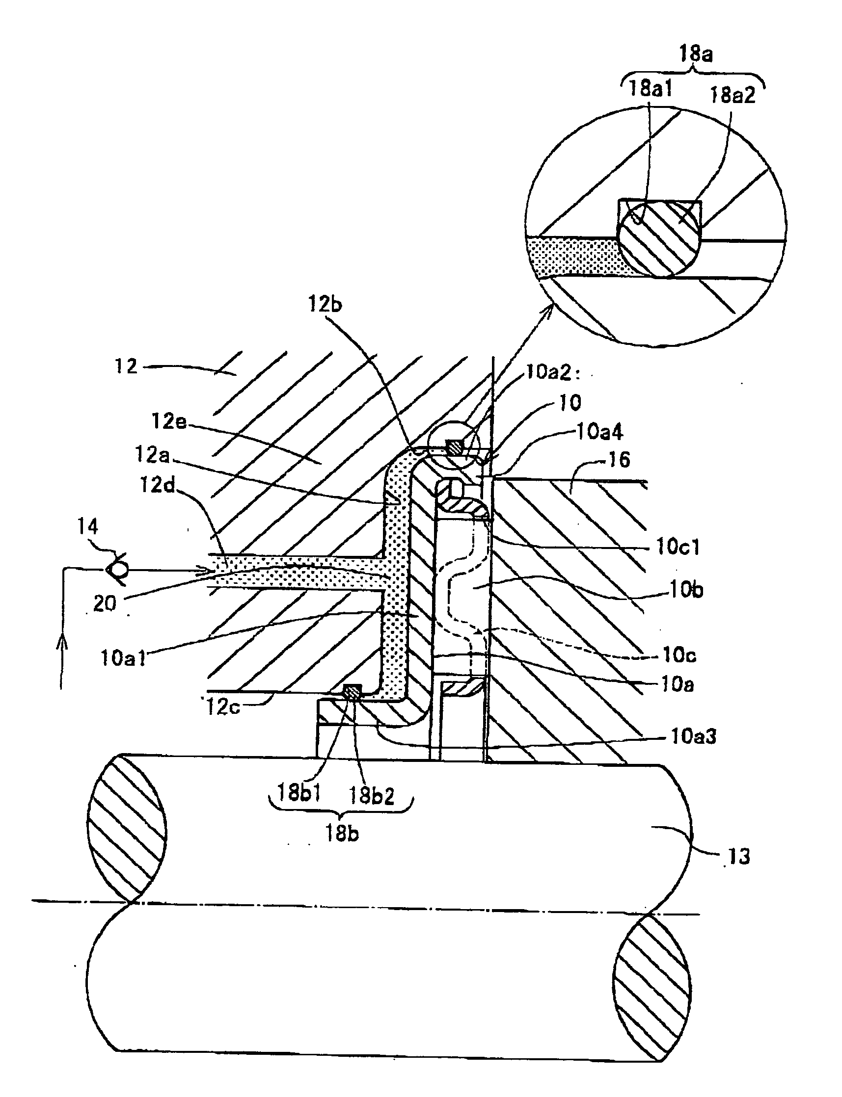
[0015] Referring to FIG. 1, a thrust roller bearing 10 is installed in the inside of a housing (a mating member) 12 of an automatic transmission, The housing 12 has an annular bottom wall surface 12a, an annular outside diameter-side or radially outside side wall surface 12b which rises in an axial direction from a radially outside circumferential edge portion of the bottom surface wall 12a and an annular inside diameter-side or radially inside side wall surface 12c which descends in the other axial direction from a radially inside circumferential edge portion of the bottom wall surface 12a.

[0016...


PUM


Abstract

A thrust roller bearing apparatus is such as to be installed in a hydraulic mechanism to adjust a gap produced between components when they are assembled in the hydraulic mechanism and is configured such that a back side of a race forms an oil pressure chamber in a space produced between the back side of the race and a mating member which the race oppositely faces, so that the race bears a pressure from the oil pressure chamber so as to be displaced axially to thereby carry out the adjustment of the gap.

Description

BACKGROUND OF THE INVENTION [0001] The present invention relates to a thrust roller bearing apparatus which is installed in a hydraulic mechanism which operates by virtue of oil pressure such as an automatic transmission for a motor vehicle so as to adjust an axial gap which occurs between components making up the hydraulic mechanism when the respective components are assembled thereinto, the gap occurring due to the dispersion in axial dimensions thereof. [0002] Automatic transmissions using torque converters are how becoming a main stream of automatic transmissions. The automatic transmissions are constructed by assembling a number of transmission components along axial directions of an input shaft and an output shaft which are installed in a housing thereof However, due to dimensional dispersion present in relation to width dimensions and assembly dimensions of the respective components, a slight gap (assembly gap) of on the order of 1 mm is generated between components which is ...

Claims


Application Information

Patent Timeline
IPC IPC(8): F16C33/34
CPCF16C19/30F16C25/06F16C35/067F16C35/078F16C19/46F16C25/08
Inventor TAKAMIZAWA, WATARUSATO, HIROSHI
Owner JTEKT CORP
Learn More