Holographic recording system and optical chopper

a recording system and optical hopper technology, applied in the field of optical hoppers and optical recording systems, can solve the problems of complex structure, high fabrication cost, and the inability of recording beams to reliably follow recording mediums, and achieve the effect of simple structure and reliably following recording mediums

Inactive Publication Date: 2006-06-29
TDK CORPARATION
View PDF3 Cites 9 Cited by
  • Summary
  • Abstract
  • Description
  • Claims
  • Application Information

AI Technical Summary

Benefits of technology

[0008] The present invention addresses the above-described problems in the conventional technology, with an object of providing a holographic recording system and an optical chopper that have a simple structure and can make the record beam reliably follow a recording medium even if the recording medium is moved at high speed.
[0009] As a result of diligent research, the present inventor has found that holographic recording is possible so that the recording beam can be irradiated to an identical position in the holographic recording medium, by using a chopper lens traveling in synchronization with the holographic recording medium and deflecting a recording beam according to its incident positions on the chopper lens.

Problems solved by technology

Therefore, the structure is complicated, the fabrication cost is high, and there is a risk that the recording beam cannot reliably follow the recording medium when the recording medium is rotated at high speed.

Method used


Image

  • Holographic recording system and optical chopper
  • Holographic recording system and optical chopper
  • Holographic recording system and optical chopper

Examples


Embodiment Construction

[0026] An exemplary embodiment of the invention will now be described in detail with reference to the attached drawings.

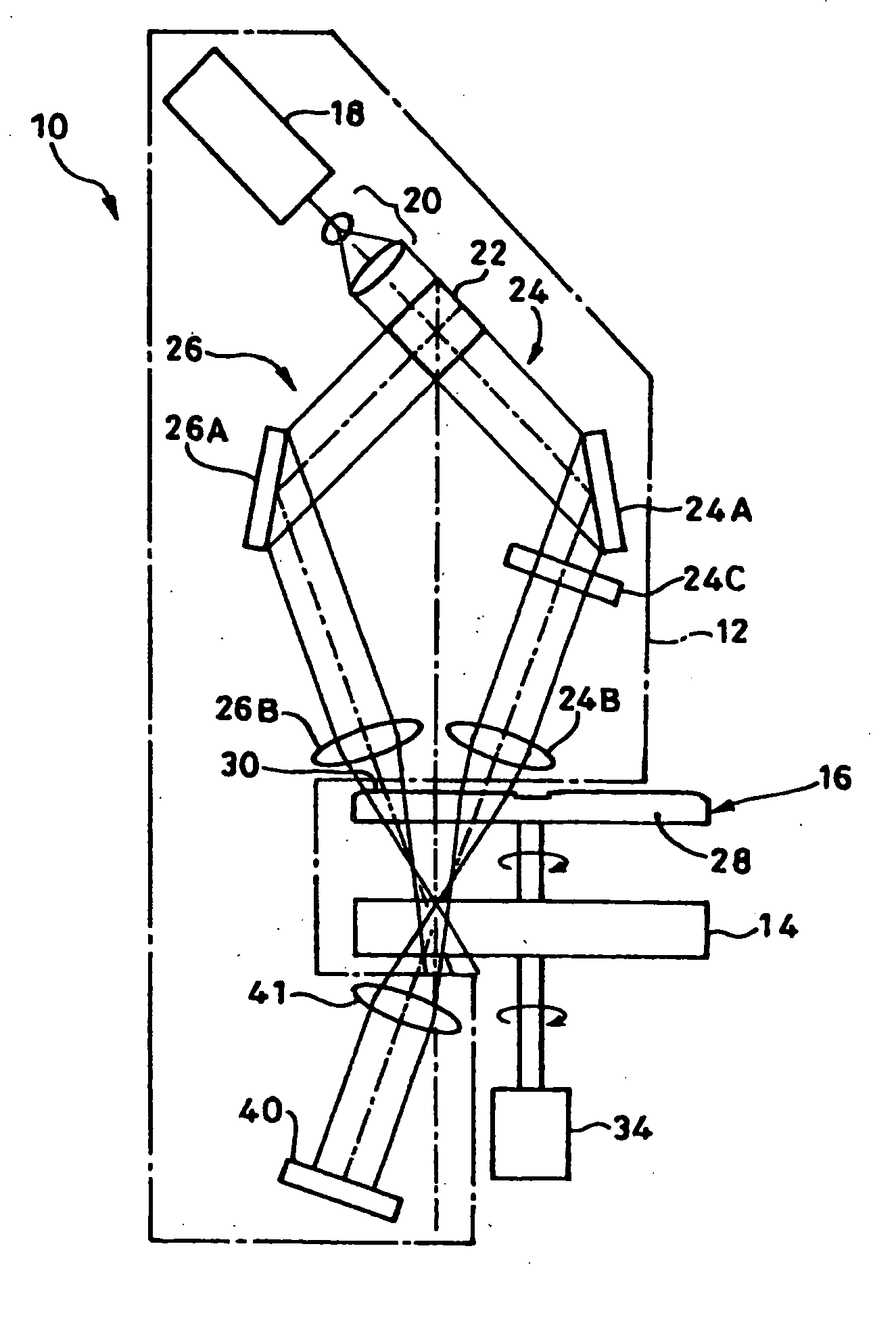
[0027] As shown in FIG. 1, a holographic recording system 10 according to the exemplary embodiment of the invention comprises: an optical head 12 that is a light irradiation unit; a holographic recording medium 14; and an optical chopper 16 that is an optical axis moving unit. An interference pattern formed by information and reference beams from the optical head 12 is recorded in the holographic recording medium 14 as a diffraction grating. The optical chopper 16 is provided on the optical axes of the information and reference beams between the optical head 12 and the holographic recording medium 14, and functions as an optical axis shifting unit which moves the optical axes while making these information and reference beams be in synchronization with the movement of the holographic recording medium 14.

[0028] The optical head 12 comprises: a laser light source 1...


PUM


Abstract

A holographic recording system with a simple structure is provided that can make a holographic recording beam follow a recording medium traveling even at high speed. The holographic recording system 10 includes a chopper lens 30 that travels in synchronization with and in a same direction as the holographic recording medium 14. The chopper lens 30 is formed so as to move the axes of incident information and reference beams relative to the recording medium and the chopper lens, and to irradiate them to an identical information recording region 15 in the holographic recording medium 14.

Description

TECHNICAL FIELD [0001] The present invention relates to a holographic recording system and an optical chopper that utilize holography to record information into a holographic recording medium. BACKGROUND ART [0002] In holographic recording that utilizes holography to record information into a recording medium, an information beam and a reference beam are superposed each other in a holographic recording medium and an optical interference pattern formed by these beams is written as a diffraction grating. [0003] As one of holographic recording systems, there is a system that modulates a recording beam comprising the information and reference beams in time and space and irradiates it to a recording medium while continuously moving the recording medium with respect to the optical axis of the recording beam. This includes, for example, a holographic recording system that irradiates the recording beam from an optical head while rotating a disc-shaped recording medium. [0004] In this case, ...

Claims


Application Information

Patent Timeline
IPC IPC(8): G11B7/00G03H1/04G02B26/04G03H1/26G11B7/0045G11B7/0065G11B7/1374G11B7/1378
CPCG02B26/04G03H1/26G03H1/265G11B7/1374G11B7/1378
Inventor TSUKAGOSHI, TAKUYAYOSHINARI, JIRO
Owner TDK CORPARATION
Why Eureka
Try Eureka