Projection video display apparatus and brightness adjustment method therefor

a technology of projection video and display apparatus, which is applied in the direction of projectors, color television details, instruments, etc., can solve the problems of cumbersome determination processes that are required, and achieve the effect of accurately controlling brightness/darkness and suppressing shadows on projection images

Inactive Publication Date: 2006-06-29
KK TOSHIBA
View PDF11 Cites 51 Cited by
  • Summary
  • Abstract
  • Description
  • Claims
  • Application Information

AI Technical Summary

Benefits of technology

[0007] It is an object of the present invention to provide a projection video display apparatus and brightness adjustment method therefor capable of suppressing a shadow on a projection image, and accurately controlling brightness / darkness as required, even when a two-dimensional LED light source is used.

Problems solved by technology

Hence, in order to adjust the brightness / darkness, cumbersome determination processes are required.

Method used


Image

  • Projection video display apparatus and brightness adjustment method therefor
  • Projection video display apparatus and brightness adjustment method therefor
  • Projection video display apparatus and brightness adjustment method therefor

Examples


Embodiment Construction

[0019] An embodiment of the present invention will be described in detail below with reference to the accompanying drawing.

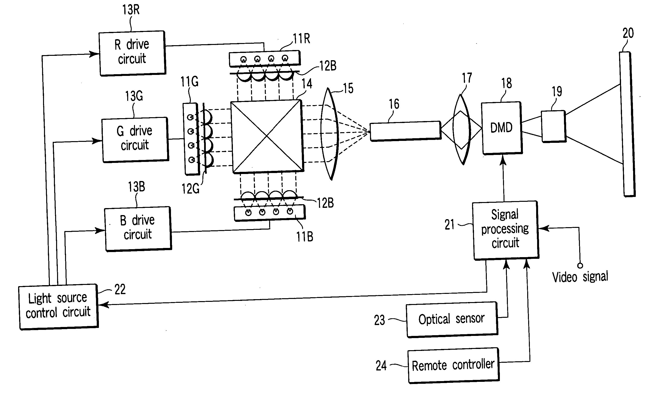
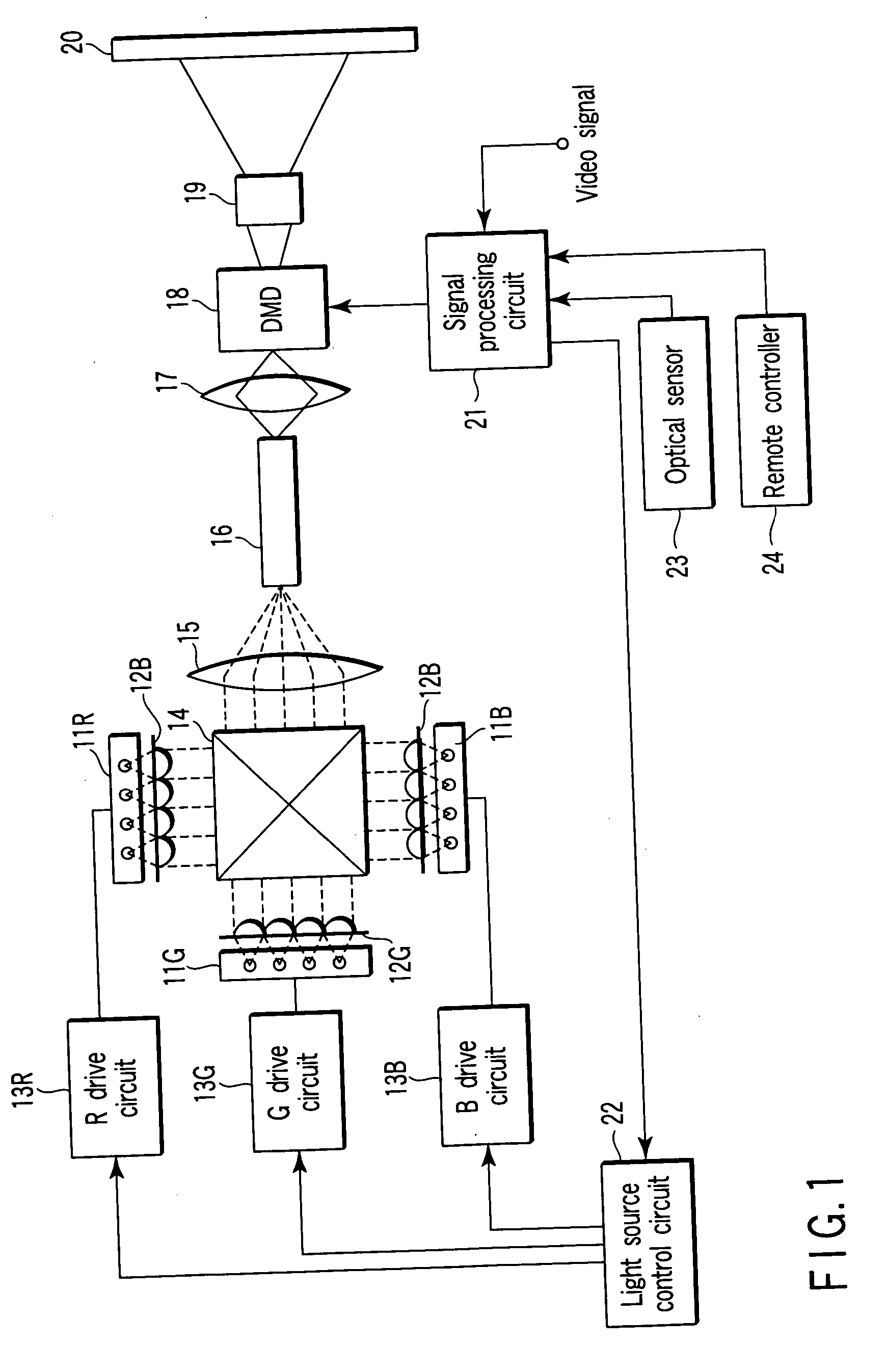
[0020]FIG. 1 shows an arrangement example of a projection video display apparatus according to the present invention. Reference numerals 11R, 11G, and 11B denote LED light sources each of which has a predetermined number of two-dimensionally arrayed LEDs. On the light-emitting surfaces of the LED light sources, color filters 12R, 12G, and 12B corresponding to R, G, and B are respectively mounted.

[0021] The LED light sources 11R, 11G, and 11B are connected to corresponding LED drive circuits 13R, 13G, and 13B, and sequentially emit light beams at predetermined time intervals in accordance with driving signals from the LED drive circuits 13R, 13G, and 13B, respectively. The LEDs included in each of the LED light sources 11R, 11G, and 11B are individually ON / OFF driven by the LED drive circuits 13R, 13G, and 13B.

[0022] The light beams emitted from the LED light ...


PUM


Abstract

This invention is applied to a projection video display apparatus which causes a DMA to modulate light from a light source having a plurality of two-dimensionally arrayed LEDs in accordance with a video signal and projects the modulated video light onto a screen via a projection optical lens. The two-dimensionally arrayed LEDs are sequentially turned off from outside to inside when a drive device for ON/OFF-driving the LEDs of the light source is designated to darken the light source. Alternatively, the two-dimensionally arrayed light-emitting elements are sequentially turned on from inside to outside when the drive device is designated to brighten the light source.

Description

CROSS-REFERENCE TO RELATED APPLICATIONS [0001] This application is based upon and claims the benefit of priority from prior Japanese Patent Application No. 2004-378183, filed Dec. 27, 2004, the entire contents of which are incorporated herein by reference. BACKGROUND OF THE INVENTION [0002] 1. Field of the Invention [0003] The present invention relates to a projection video display apparatus which uses an optical space modification element such as a digital micromirror device (DMD). [0004] 2. Description of the Related Art [0005] As a space modification element, a projection video display apparatus which uses a digital micromirror device (DMD) is available. Conventionally, this type of video display apparatus uses a lamp as a light source. However, recently, the video display apparatus uses two-dimensionally arrayed LEDs (Light-Emitting Diodes) as one light source (e.g., Jpn. Pat. Appln. KOKAI Publication No. 10-269802). [0006] In the two-dimensional LED light source, brightness / dar...

Claims


Application Information

Patent Timeline
Patent Type & Authority Applications(United States)
IPC IPC(8): G09G3/28G03B21/00G03B21/14
CPCG03B21/00G09G3/002G09G3/3426G09G2320/0606G09G2320/064G09G2320/0666G09G2360/144H04N9/3155G03B21/2053G03B21/008
Inventor SUGIYAMA, TOORU
Owner KK TOSHIBA
Why Eureka
Try Eureka