
Press-hardened part and method for the production thereof

a press-hardened part and press-hardening technology, which is applied in the direction of heat treatment furnaces, heat treatment equipment, furnaces, etc., can solve the problems of rapid crack formation in the part, high tool wear and high maintenance costs, and the cutting method works comparatively slowly, so as to improve the method sequence and reduce the cycle time irrespective of the length of the part outer contour

Active Publication Date: 2006-06-29
DAIMLER AG
View PDF9 Cites 38 Cited by
  • Summary
  • Abstract
  • Description
  • Claims
  • Application Information

AI Technical Summary

Benefits of technology

[0008] The object of the invention is therefore to improve the method sequence during the production of parts of hot-workable sheets to the effect that the cycle time—irrespective of the length of the part outer contour—can be reduced.

Problems solved by technology

However, in order to cut a part produced in this way in a dimensionally accurate manner, a large outlay in terms of equipment is required: in particular, very high cutting forces are required for the cold cutting of hardened materials, which leads to rapid tool wear and high maintenance costs.
Furthermore, the cold trimming of such high-strength parts is problematical, since, for example, the part edges trimmed in the cold state have more or less large burrs, a factor which may lead to rapid crack formation in the part on account of the high notch sensitivity of the high-strength materials.
High-quality trimming of the edge of the parts can certainly be achieved by means of these methods, but these cutting methods work comparatively slowly, since the cycle times here depend directly on the length of the cut edge and on the tolerances to be maintained.
The final trimming process therefore produces a bottleneck during the production of hot-formed parts, which limits the number of parts to be produced per unit of time.
The total cycle time of the part production can certainly be reduced if—depending on the length of the cut edge—a plurality of laser or water-jet cutting units working in parallel are provided; however, this involves high additional investment and logistics outlay and is therefore disadvantageous.

Method used


Image

  • Press-hardened part and method for the production thereof
  • Press-hardened part and method for the production thereof
  • Press-hardened part and method for the production thereof

Examples


Embodiment Construction

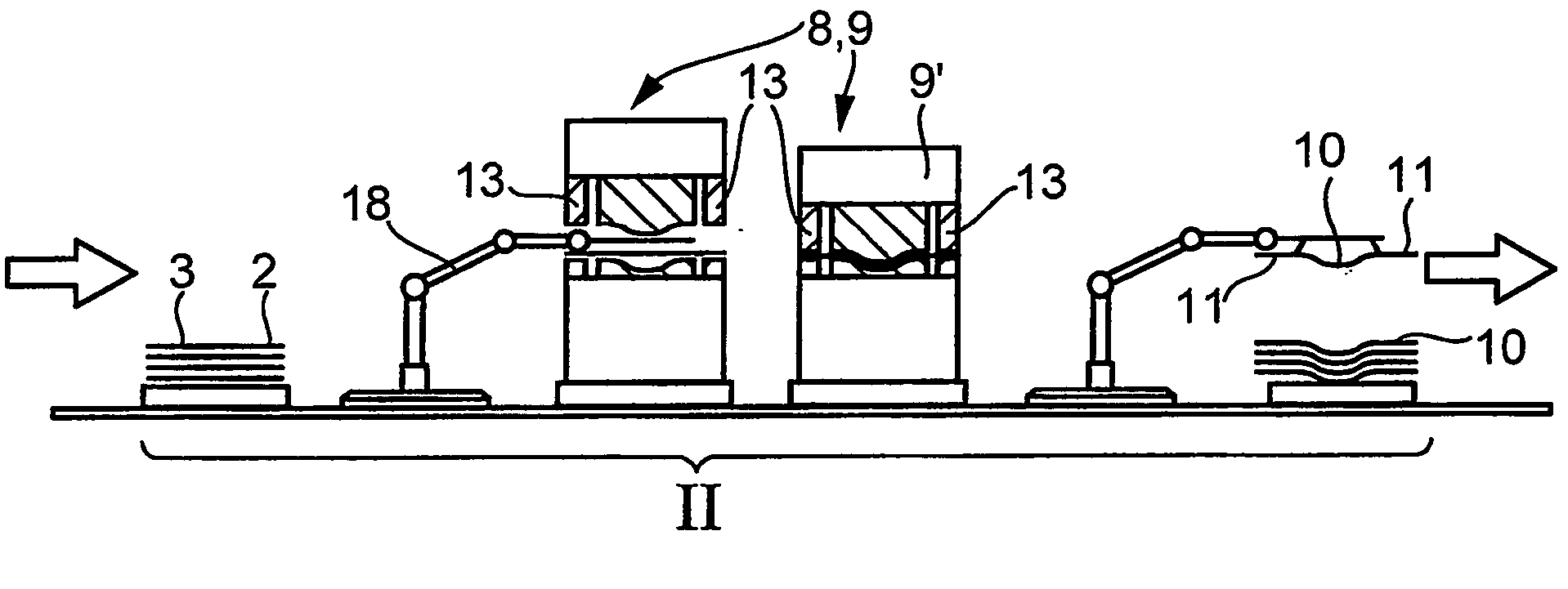
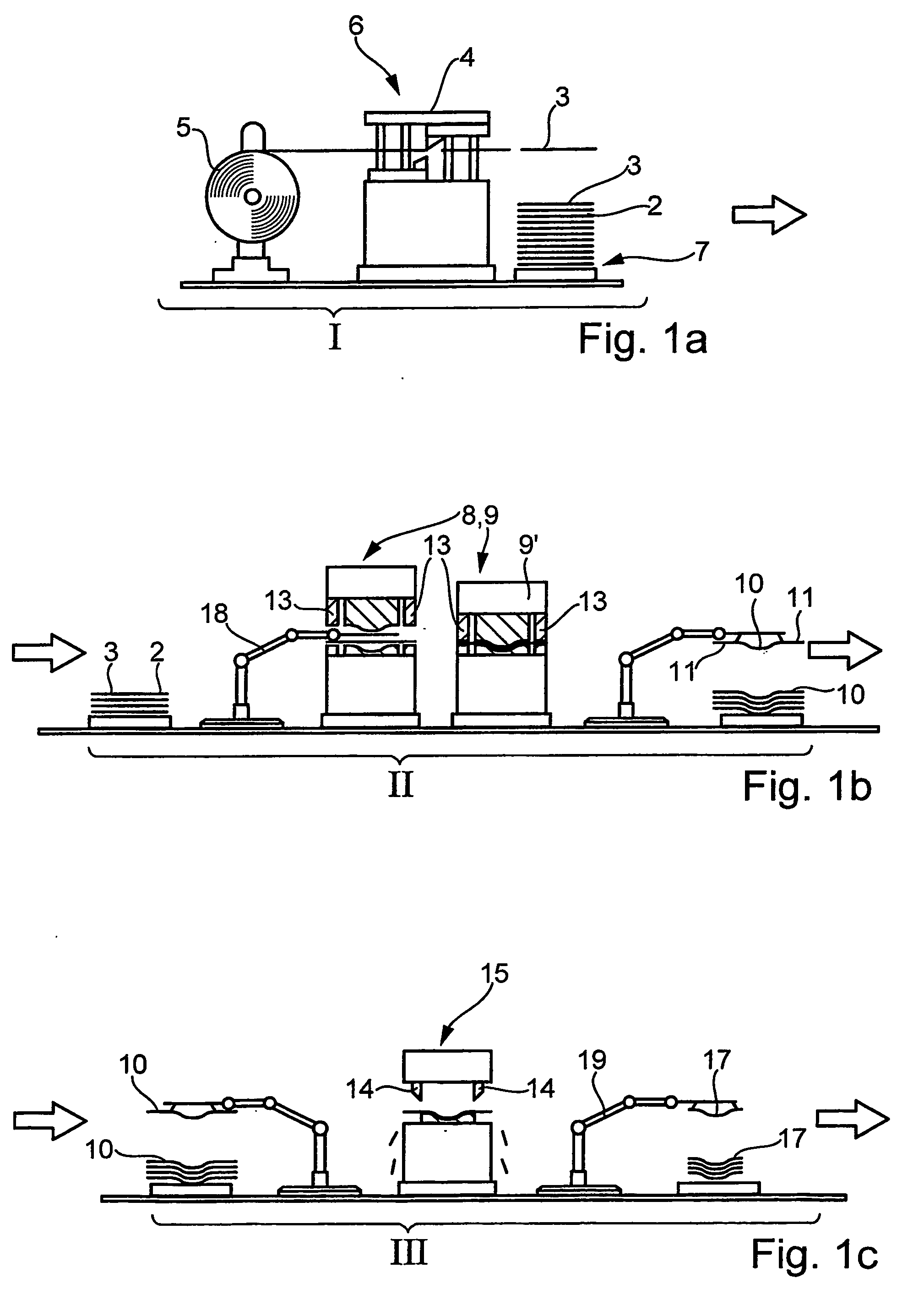
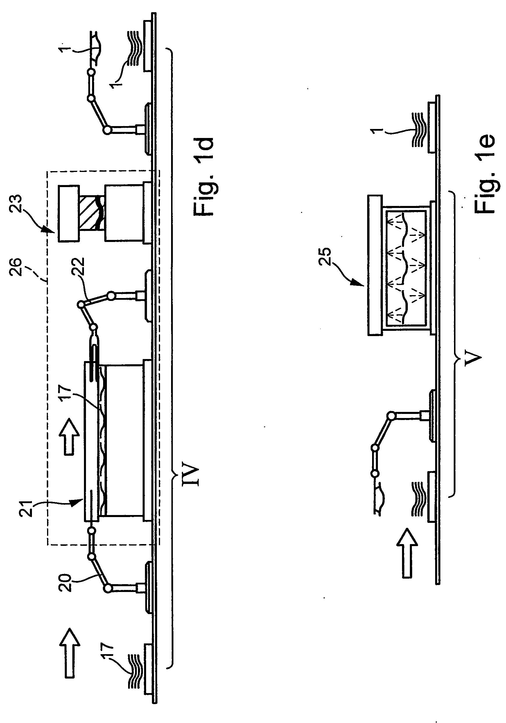
[0036]FIGS. 1a to 1e schematically show the method according to the invention for producing a three-dimensionally shaped, press-hardened part 1 from a semifinished product 2. In the present exemplary embodiment, the semifinished product 2 used is a sheet blank 3 which is cut out of an unwound sheet coil. Alternatively, the semifinished product used may be a composite sheet which—as described, for example, in DE 100 49 660 A1—consists of a base sheet and at least one reinforcing sheet. Furthermore, the semifinished product used may be a tailored blank which consists of a plurality of welded-together sheets of different material thickness and / or different material constitution. Alternatively, the semifinished product may be a three-dimensionally shaped sheet-metal part which is produced by any desired forming method and which is to be subjected to further forming and a strength / rigidity increase by means of the method according to the invention.

[0037] The semifinished product 2 consi...


PUM

PropertyMeasurementUnit
Temperatureaaaaaaaaaa
Metallic bondaaaaaaaaaa

Abstract

To produce a metallic shaped part (1), in particular a vehicle body part, from a semifinished product (2) made of an unhardened hot-workable steel sheet, first of all the semifinished product (2) is formed by a cold-forming method, in particular a drawing method, into a part blank (10) (process step II). The part blank (10) is then trimmed at the margins to a marginal contour (12′) approximately corresponding to the part (1) to be produced (process step III). Finally, the trimmed part blank (17) is heated and press-hardened in a hot-forming tool (23) (process step IV). The part (1) produced in the process already has the desired marginal contour (24) after the hot forming, so that the final trimming of the part margin is dispensed with. In this way, the cycle times during the production of hardened parts of steel sheet can be considerably reduced.

Description

BACKGROUND OF THE INVENTION [0001] 1. Field of the Invention [0002] The invention relates to a method of producing a metallic shaped part, in particular a vehicle body part, from a semifinished product made of an unhardened hot-workable steel sheet. [0003] 2. Related Art of the Invention [0004] Many parts, in particular body parts in vehicle construction, must satisfy stringent requirements with regard to rigidity and strength. At the same time, in the interests of weight reduction, the parts are to have as small a material thickness as possible. In order to meet these two requirements, high-strength and super-high-strength steel materials, which—depending on composition and heat treatment—have very high strength, are being increasingly used. The production of vehicle body parts from these super-high-strength steel sheets is preferably effected in a hot-forming process, in which—as described, for example, in DE 100 49 660 A1—a sheet blank is heated and then shaped in a special shapi...

Claims


Application Information

Patent Timeline
IPC IPC(8): C21D8/00B21D22/26B21D22/20B21D24/00B21D28/00B21D35/00B21D53/88C21D1/18C21D1/673C21D1/70C21D7/13C21D9/00C22C38/00C22C38/58
CPCB21D35/00B21D53/88C21D1/673C21D7/13
Inventor BRODT, MARTINFISCHER, UWEMEHRHOLZ, RALF
Owner DAIMLER AG
Learn More