
Pivotable needle unit

a needle unit and pivoting technology, applied in the field of pivoting needle units, can solve the problems of increasing complexity, affecting the actual user's ability to pierce the tissue with the needle, and affecting the accuracy of piercing, so as to achieve a high degree of flexibility and reliability

Inactive Publication Date: 2006-06-22
NOVO NORDISK AS
View PDF18 Cites 212 Cited by
  • Summary
  • Abstract
  • Description
  • Claims
  • Application Information

AI Technical Summary

Benefits of technology

[0017] Correspondingly, a medical device is provided, comprising a housing having a mounting surface adapted for application to the skin of a subject, and a transcutaneous device unit connected to the housing thereby providing a hinge allowing the needle unit or a portion thereof to pivot corresponding to a pivoting axis defined by the hinge, the pivoting axis being arranged substantially in parallel with the mounting surface. The transcutaneous device unit comprises a transcutaneous device, the transcutaneous device comprising a distal pointed portion adapted to penetrate the skin of the subject, the distal portion extending generally perpendicular to the mounting surface, and a proximal portion arranged substantially corresponding to the pivoting axis, whereby the transcutaneous device unit is arranged to provide a pivoting movement between a first position in which the distal portion of the needle is retracted within the housing, and a second position in which the inlet portion projects relative to the mounting surface. The hinge may be formed by the unit or between the unit and the housing. In this way the invention provides a transcutaneous device unit which can be actuated and connected without relying on sliding (e.g. linear) movement of the transcutaneous device unit and without having to bent the transcutaneous device.
[0019] By this arrangement a distal end of a transcutaneous device can be moved between a retracted state and an extended state, yet providing a proximal end allowing a high degree of flexibility and reliability for connection to a fluid reservoir. For example, a fluid reservoir may be (or may be brought) in fluid communication with proximal end of the transcutaneous device before the needle unit is pivoted, or the fluid reservoir may be brought in fluid communication with the proximal end of the transcutaneous device during or after the transcutaneous device unit is pivoting. The only requirement for allowing this arrangement would be that the fluid connection allows rotation of the proximal transcutaneous device end and is moved axially corresponding to the pivoting axis.

Problems solved by technology

The first class comprises durable infusion pumps which are relatively expensive pumps intended for 3-4 years use, for which reason the initial cost for such a pump often is a barrier to this type of therapy.
Al-though this configuration provides a simple and cost-effective solution, the actual user-performed piercing of the tissue with the needle is often problematic as people who are not experts in medicine are usually insufficiently practised to place such a needle correctly and they often suffer from a fear of the likely pain.
Although the automatic needle insertion means adds convenience for the user and may serve to overcome needle fear, such means also adds to the complexity and thus to the cost of the device, they may reduce the reliability, just as they may add to the bulkiness of the device.
In the above primarily infusion devices has been discussed, however, the problem of inserting a needle-formed device through the skin of a subject also relates to other fields, e.g. the introduction of needle-formed sensors comprising sensor means capable of being influenced by a body substance and producing a signal corresponding thereto (e.g. blood glucose).

Method used


Image

  • Pivotable needle unit
  • Pivotable needle unit
  • Pivotable needle unit

Examples


Embodiment Construction

[0054] When in the following terms as “upper” and “lower”, “right” and “left”, “horizontal”and “vertical” or similar relative expressions are used, these only refer to the appended figures and not to an actual situation of use.

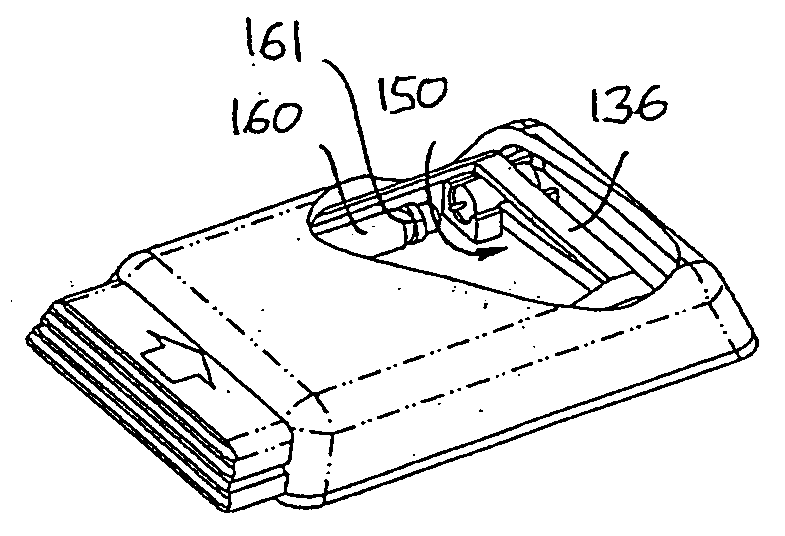
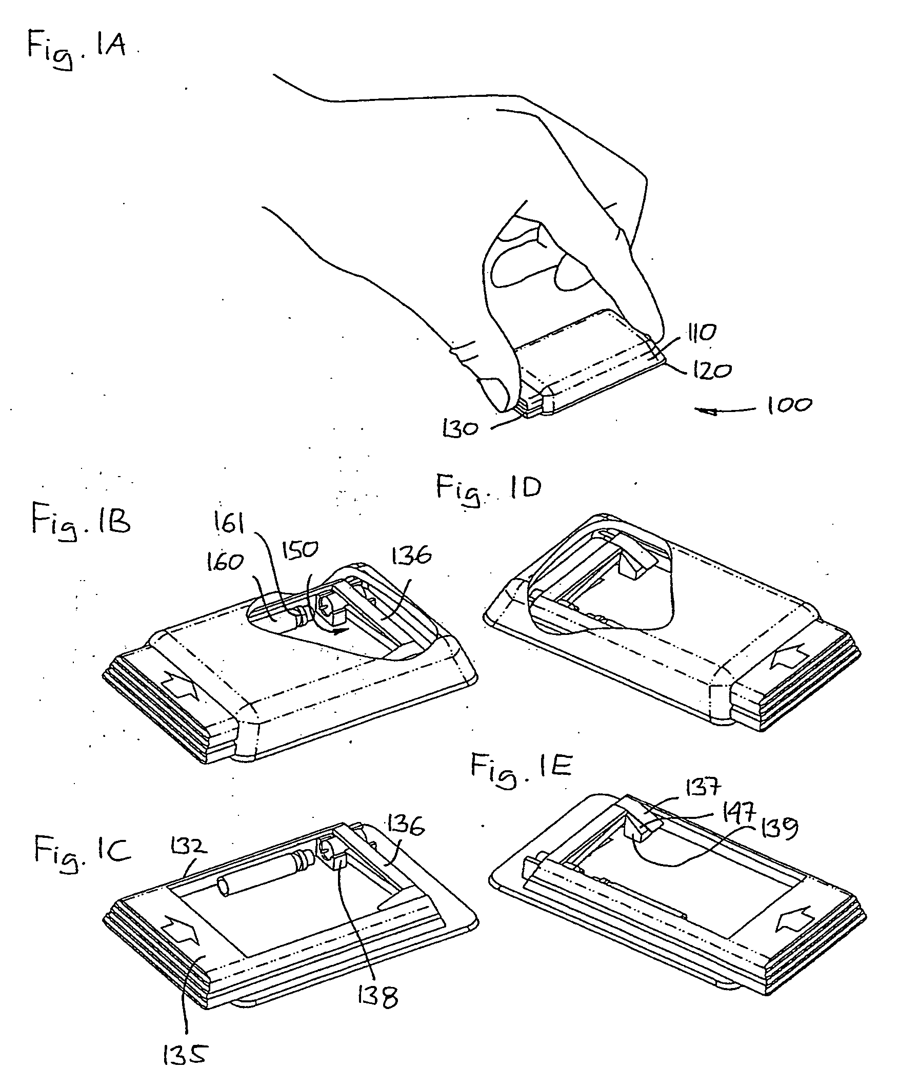
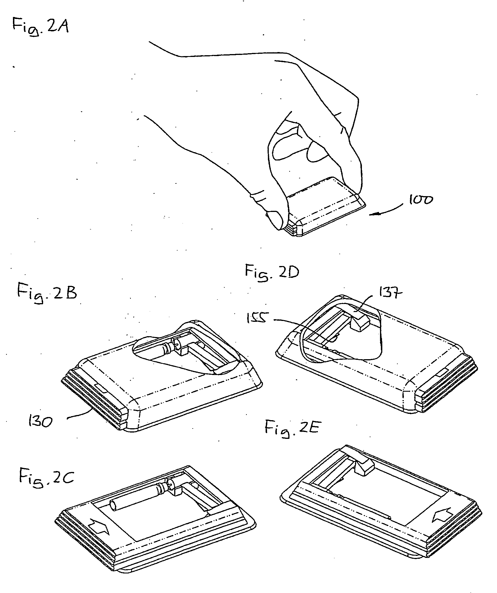
[0055]FIGS. 1-3 show in schematic representations perspective views of different states of use of a medical device in accordance with the invention. Correspondingly, the configuration of the different structures as well as there relative dimensions are intended to serve illustrative purposes only.

[0056] More specifically, FIG. 1A shows a first embodiment of a medical device 100 gripped by a user. The medical device comprises a housing with an upper housing portion 110 and a lower base plate portion 120, the housing providing a cavity in which an actuation member 130 is slidingly received through an opening, the actuation element being moveable corresponding to a longitudinal direction in respect of the device. The base plate portion comprises an adhesive mou...


PUM


Abstract

The present invention generally relates to the insertion of needles or needle-like members. Thus, a device comprises a housing having a mounting surface adapted for application to the skin of a subject, and a needle unit connected to the housing by a hinge allowing the needle unit to pivot corresponding to a pivoting axis defined by the hinge, the pivoting axis being arranged substantially in parallel with the mounting surface. The needle unit comprises a needle having a distal pointed portion adapted to penetrate the skin of the subject, the distal portion extending generally perpendicular to the mounting surface, and a proximal portion arranged substantially corresponding to the pivoting axis, whereby the needle unit is arranged to pivot between a first position in which the distal portion of the needle is retracted within the housing, and a second position in which the distal portion projects relative to the mounting surface. The needle may e.g. be in the form of a hollow needle or a needle sensor.

Description

CROSS REFERENCE TO RELATED APPLICATIONS [0001] This application is a continuation of international application serial no. PCT / DK2004 / 000332 filed May 10, 2004 and claims priority of Danish application no. PA 2003 00696 filed May 8, 2003 and U.S. provisional application No. 60 / 471,011 filed May 16, 2003, all of which are hereby incorporated by reference.[0002] The present invention generally relates to the insertion of transcutaneous devices such as needles, needle-like members and cannulas. More specifically, the invention relates to insertion of a transcutaneous device at a selected site within the body of a subject for subcutaneous, intravenous, intramuscular or intradermal delivery of a drug to the subject, the transcutaneous device being carried by a device comprising a mounting surface adapted for application to the skin of the subject. Especially, the invention relates to insertion of an infusion needle or cannula for the infusion of a drug, to insertion of a needle-formed sen...

Claims


Application Information

Patent Timeline
Patent Type & Authority Applications(United States)
IPC IPC(8): A61M37/00A61M5/142A61M5/158
CPCA61B5/6849A61M5/14248A61M5/158A61M2005/14252
Inventor ETHELFELD, ERIK WINKEL
Owner NOVO NORDISK AS
Learn More