
Systems, illumination subsystems, and methods for increasing fluorescence emitted by a fluorophore

a fluorophore and subsystem technology, applied in the field of systems, illumination subsystems, methods for increasing fluorescence emitted by fluorophores, can solve the problems of lack of definition of polarization ratio, lack of fluorescence measurement, and limited materials available for flow cytometer measurements, etc., to achieve the effect of increasing fluorescence emitted

Inactive Publication Date: 2006-06-22
LUMINEX
View PDF18 Cites 23 Cited by
  • Summary
  • Abstract
  • Description
  • Claims
  • Application Information

AI Technical Summary

Benefits of technology

[0021] An additional embodiment relates to a method for increasing fluorescence emitted by a fluorophore attached to or incorporated into particles. The method includes altering the polarization of light before the light illuminates the particles during a measurement. The altered polarization is linear polarization oriented in a non-vertical direction, circular polarization, or elliptical polarization. In one embodiment, the altered polarization has a polarization ratio of less than 100:1 with any orientation. In a different embodiment, the altered polarization has a polarization ratio of greater than 100:1 with a non-vertical orientation. Each of the embodiments of the method described above may include any other step(s) described herein.

Problems solved by technology

However, de Grooth et al. provide no definition of the polarization ratio for “linearly polarized” light.
In addition, altering the state of the polarization (such as to elliptical) of the illumination light for purposes of fluorescence measurements has not been previously performed.
However, the materials that are available for use in flow cytometer measurements are often somewhat limited.

Method used


Image

  • Systems, illumination subsystems, and methods for increasing fluorescence emitted by a fluorophore
  • Systems, illumination subsystems, and methods for increasing fluorescence emitted by a fluorophore
  • Systems, illumination subsystems, and methods for increasing fluorescence emitted by a fluorophore

Examples


Embodiment Construction

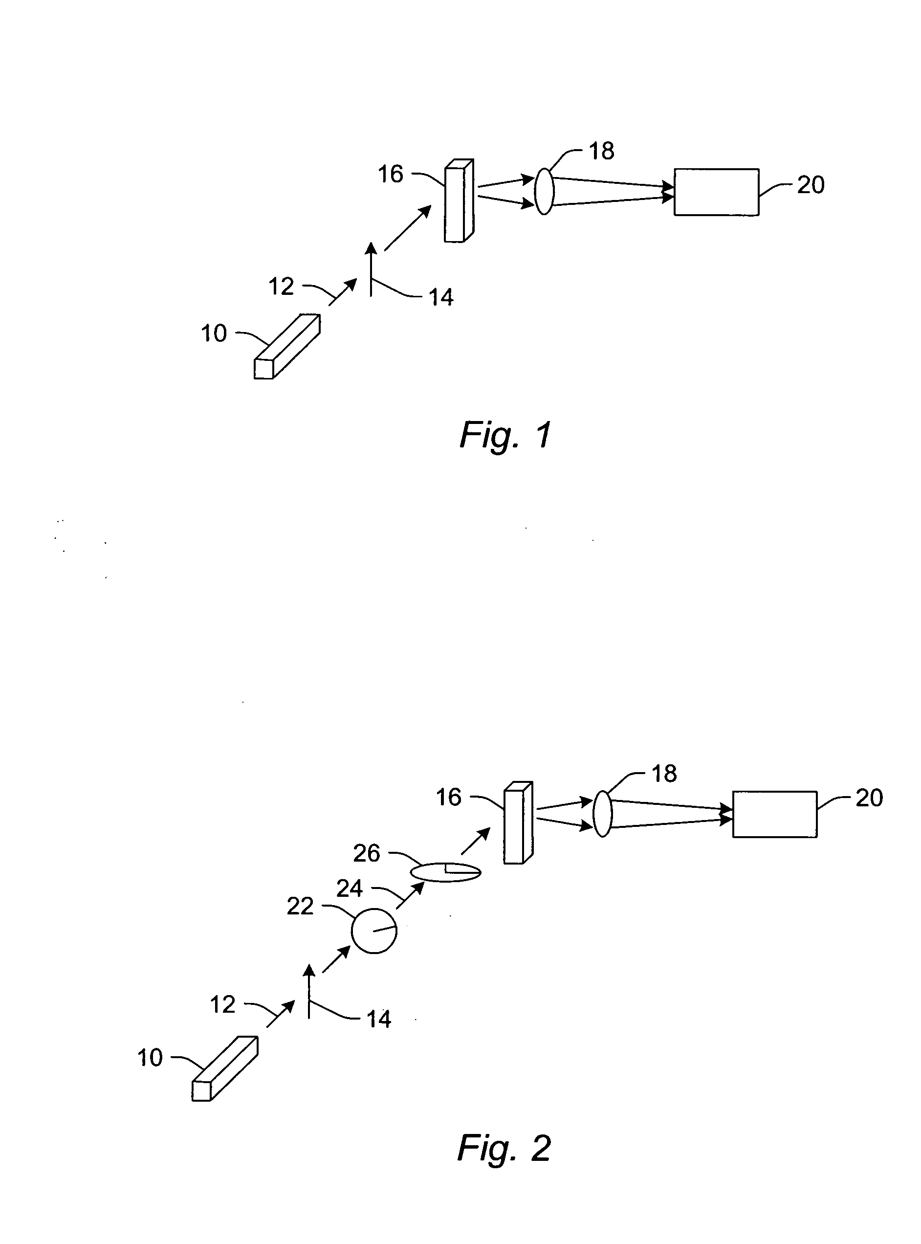
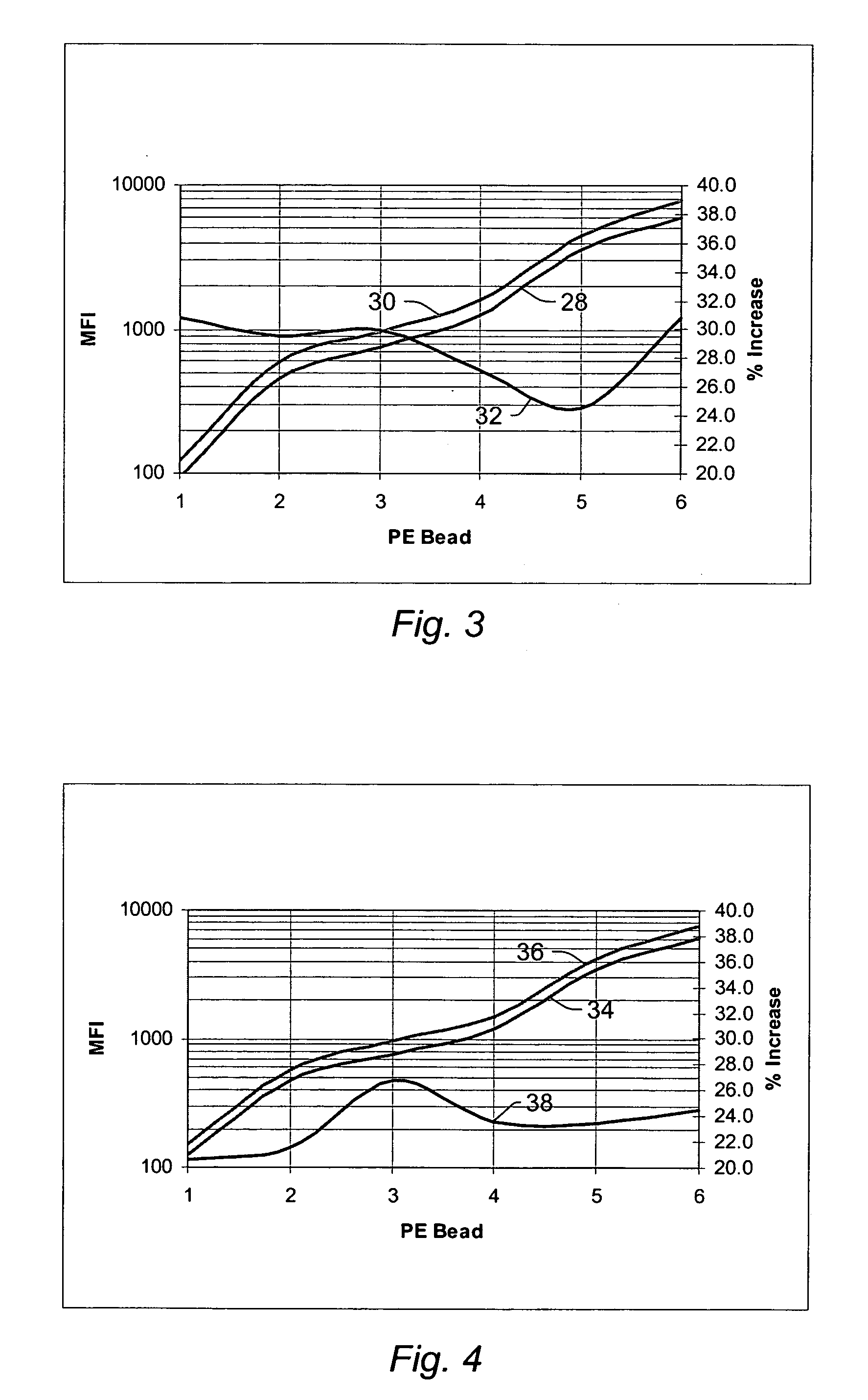
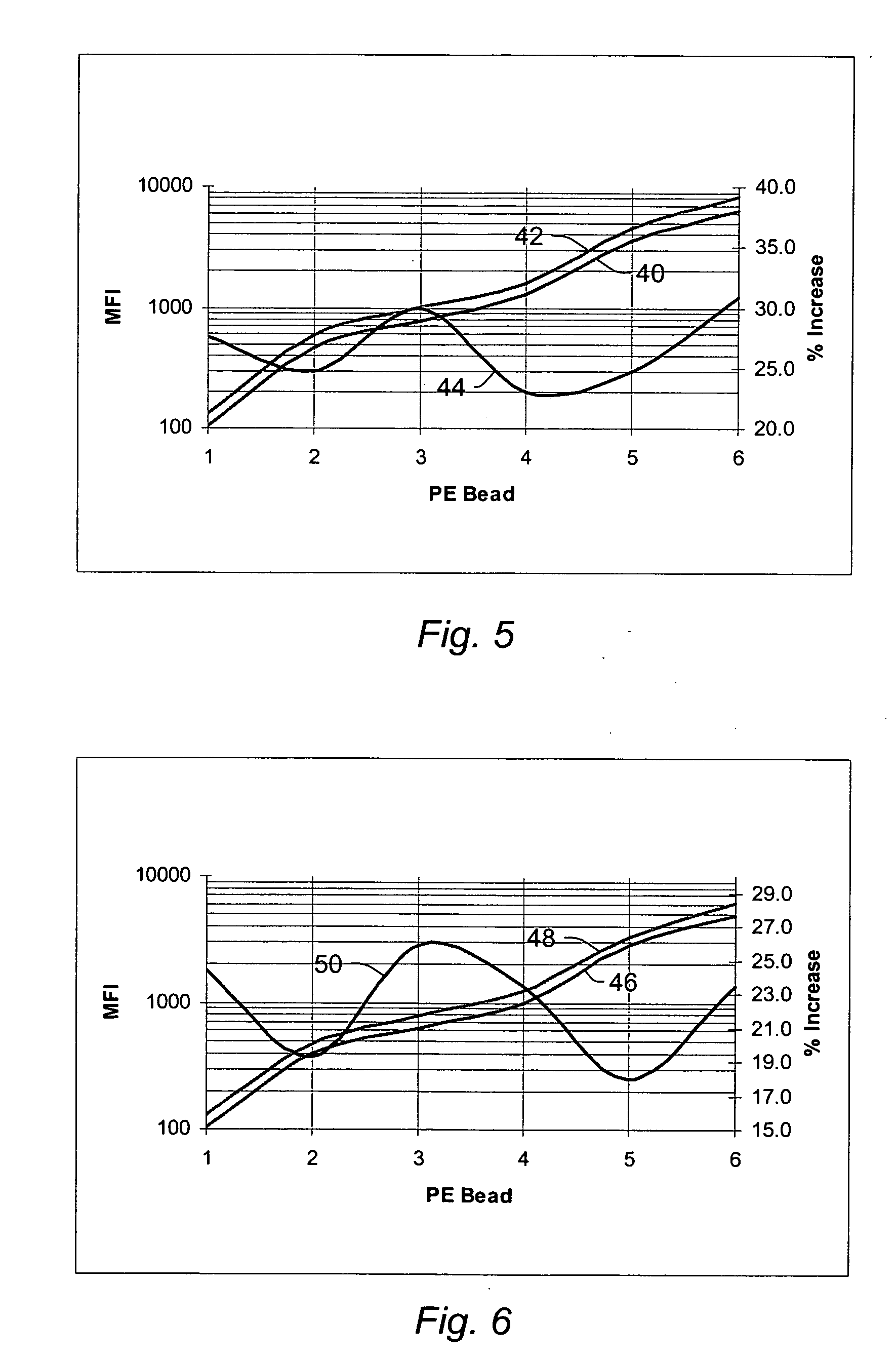
[0027] The following description generally relates to systems, illumination subsystems, and methods for obtaining increased fluorescence from fluorophores such as R-phycoerytherin (R-PE) by altering the polarization state and / or orientation (e.g., the degree of elliptical polarization) of a light beam used to illuminate the fluorophores.

[0028] Although embodiments are described herein with respect to particles, it is to be understood that the systems, illumination subsystems, and methods may also be used for microspheres, polystyrene beads, microparticles, gold nanoparticles, quantum dots, nanodots, nanoparticles, nanoshells, beads, microbeads, latex particles, latex beads, fluorescent beads, fluorescent particles, colored particles, colored beads, tissue, cells, micro-organisms, organic matter, or any non-organic matter. The particles may serve as vehicles for molecular reactions. Examples of appropriate microspheres, beads, and particles are illustrated in U.S. Pat. No. 5,736,330...


PUM

PropertyMeasurementUnit
molecular weightaaaaaaaaaa
angleaaaaaaaaaa
angleaaaaaaaaaa

Abstract

Systems, illumination subsystems, and methods for increasing fluorescence emitted by a fluorophore are provided. One system configured to measure fluorescence of particles includes an illumination subsystem configured to illuminate the particles with light having linear polarization oriented in a non-vertical direction, circular polarization, or elliptical polarization. The polarization of the light causes fluorescence emitted by the fluorophore to be brighter than fluorescence emitted by the fluorophore when illuminated with linearly polarized light oriented in a predominantly vertical direction or non-polarized light. The system also includes a detection subsystem configured to generate output signals responsive to the fluorescence emitted by the fluorophore.

Description

PRIORITY CLAIM [0001] This application claims priority to U.S. Provisional Application No. 60 / 637,355 entitled “Methods and Systems for Increasing Fluorescence from a Fluorophore,” filed Dec. 17, 2004, which is incorporated by reference as if fully set forth herein.BACKGROUND OF THE INVENTION [0002] 1. Field of the Invention The present invention generally relates to systems, illumination subsystems, and methods for increasing fluorescence emitted by a fluorophore. Certain embodiments relate to altering the polarization of the light used to illuminate particles to which a fluorophore is attached or in which a fluorophore is incorporated thereby increasing fluorescence emitted by the fluorophore. [0003] 2. Description of the Related Art [0004] The following description and examples are not admitted to be prior art by virtue of their inclusion in this section. [0005] Optical systems have been and will increasingly be used to obtain measurements for a number of different samples such a...

Claims


Application Information

Patent Timeline
Patent Type & Authority Applications(United States)
IPC IPC(8): C12M1/34G01N33/551
CPCG01N15/1434G01N15/147G01N15/1475G01N21/274G01N21/6428G01N21/6445G01N21/645G01N21/6456G01N2021/6439G01N15/1433G01N21/64G01N15/14
Inventor PHILLIPS, JESSE
Owner LUMINEX
Learn More