
System and process for forming glass-coated microwires, including a cooling system and process

a cooling system and micro-wire technology, applied in the field of system and process for forming glass-coated micro-wires, can solve the problems of undesirable variations or distortions in the uniformity and diameter of glass coating, glass-coated micro-wires may not have the proper may not have the uniformity and equilibrium of glass coating, etc., to achieve the effect of reducing uniformity and distortion

Inactive Publication Date: 2006-06-22
GLOBAL MICRO WIRE TECH
View PDF6 Cites 24 Cited by
  • Summary
  • Abstract
  • Description
  • Claims
  • Application Information

AI Technical Summary

Benefits of technology

[0009] Accordingly, one object of the present invention is to provide a novel system and process for forming a glass-coated microwire, and to provide a novel cooling system and process for a system and process for forming glass-coated microwire that can minimize or overcome the above-drawbacks in the background art.
[0010] A more specific object of the present invention is to provide a novel system and process for forming a glass-coated microwire, and novel cooling system and process for a system and process for forming glass-coated microwire in which a glass-coating with reduced uniformity and distortion can be realized.

Problems solved by technology

Specifically, the cooling system disclosed in U.S. Pat. No. 5,240,066, which causes the glass tube filled with molten metal to enter a stream of a cooling liquid to be supercooled and solidified, suffers from a drawback in that the resulting glass-coated microwire may not have the proper uniformity and equilibrium of the glass coating, and further the glass coating diameter may be distorted.
Because of the very small dimensions involved with glass-coated microwires, even such a small difference in the onset of cooling can result in undesirable variations or distortions in the uniformity and diameter of the glass coating in such produced glass-coated microwires.
Such inherent instability and turbulence in a liquid stream also results in the overall diameter of the microwire being non-uniform and / or distorted, in a system such as disclosed in U.S. Pat. No. 5,240,066.

Method used


Image

  • System and process for forming glass-coated microwires, including a cooling system and process
  • System and process for forming glass-coated microwires, including a cooling system and process
  • System and process for forming glass-coated microwires, including a cooling system and process

Examples


Embodiment Construction

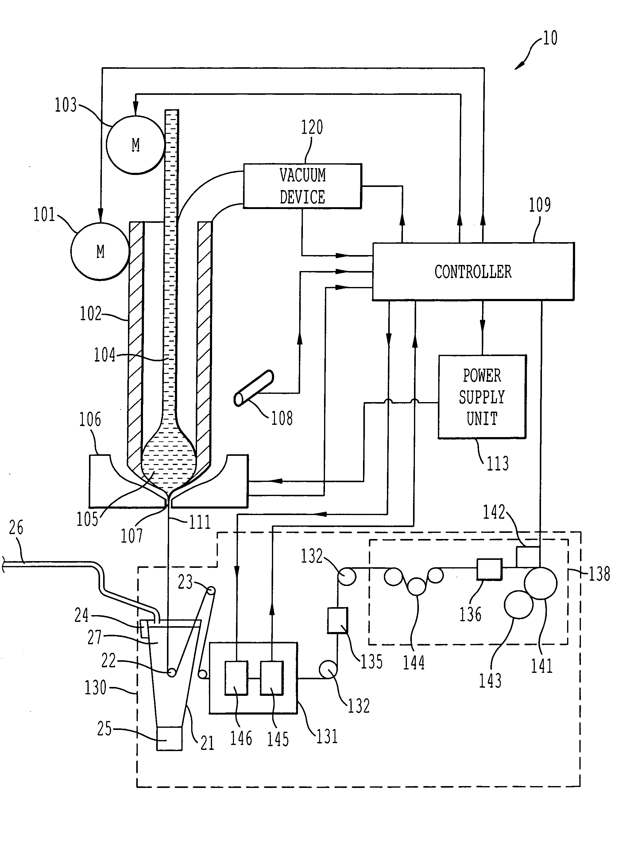
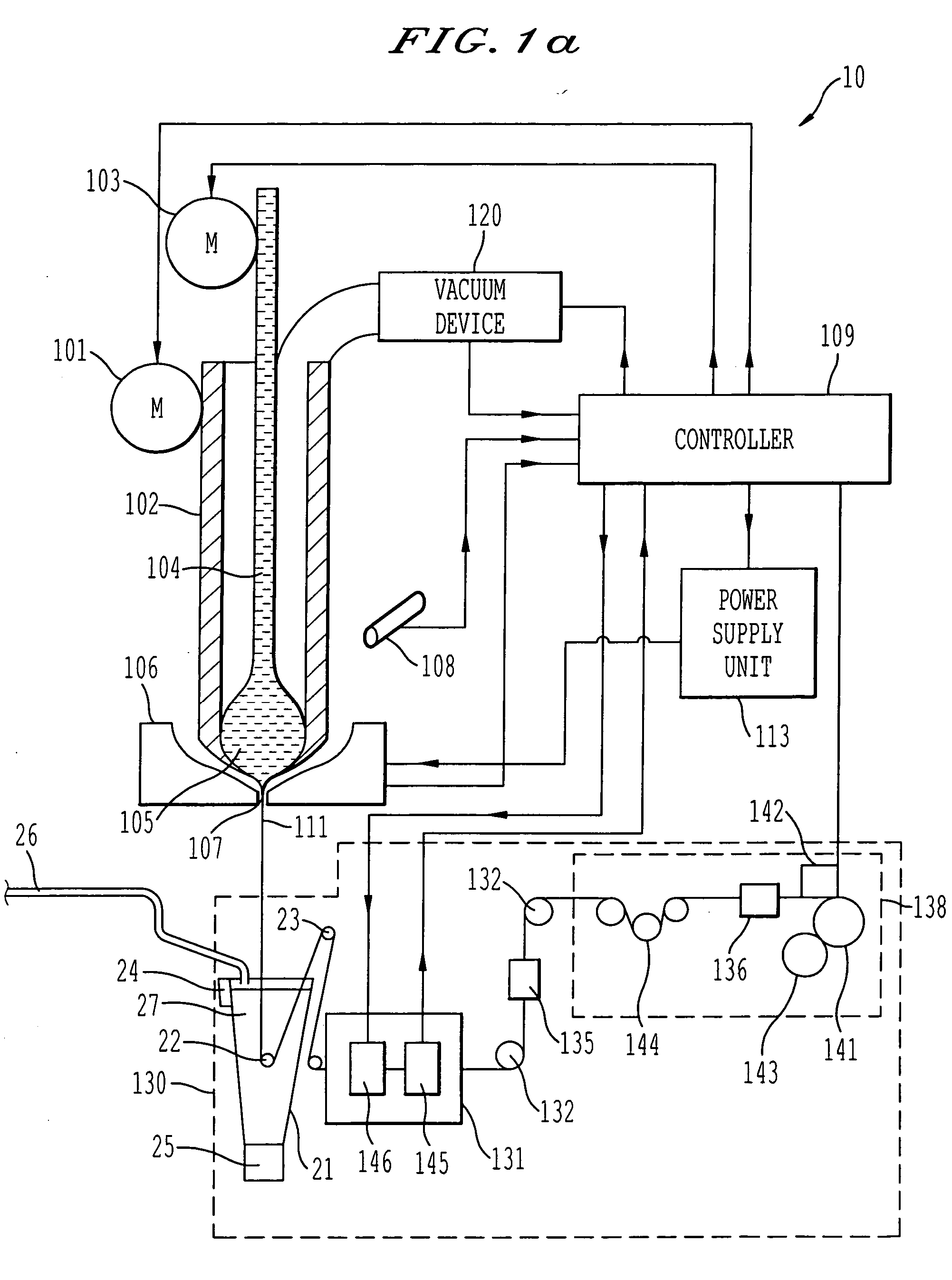
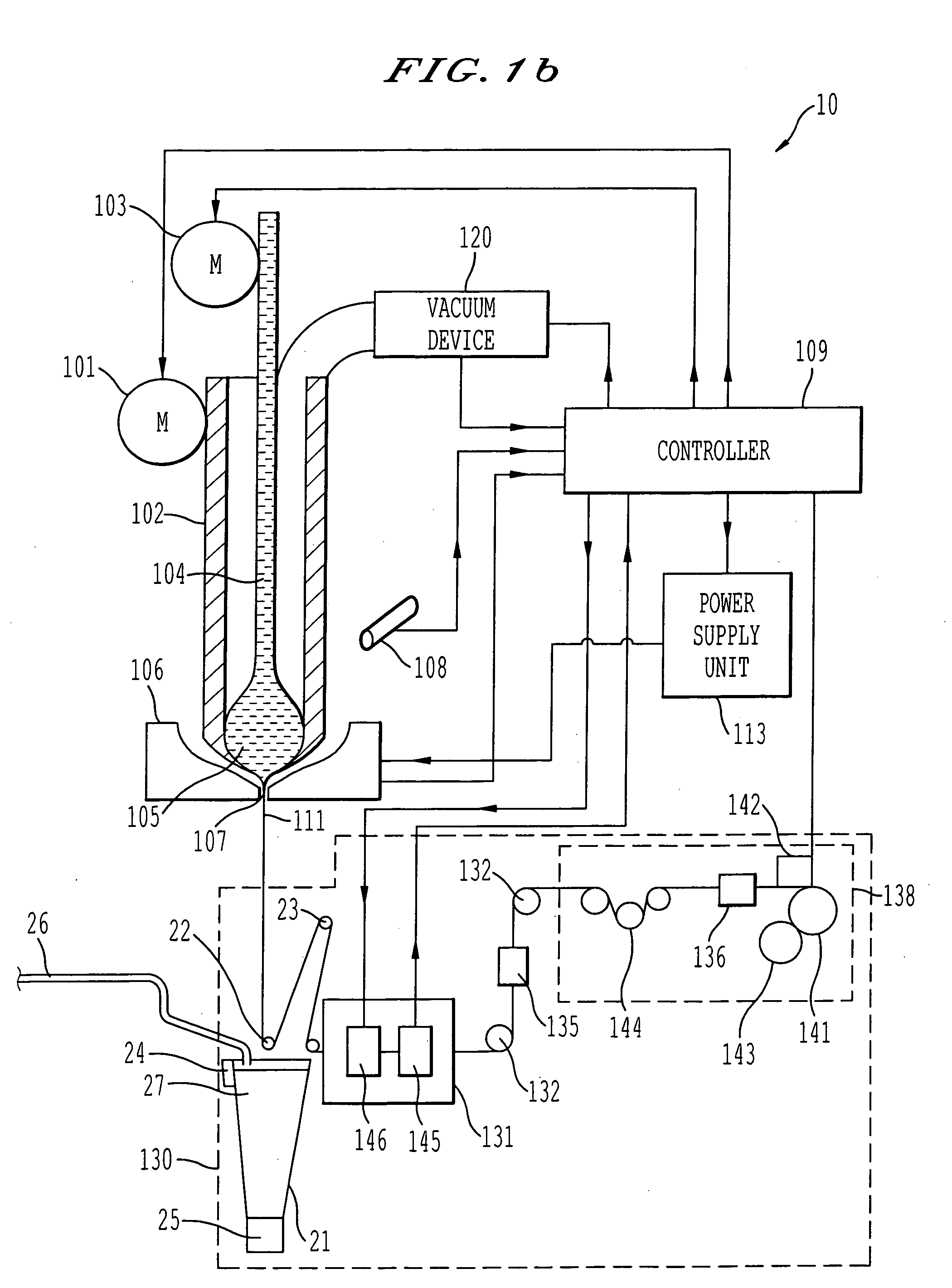
[0016] Referring now to the drawings, wherein like reference numerals designate identical or corresponding parts throughout the several views, FIGS. 1(a) and 1(b) show in overall detail a system for generating glass-coated microwire according to the present invention. The main focus of the present invention is the cooling system utilized in the system for generating glass-coated microwire, and the cooling system can be applied to different systems for generating glass-coated microwire than as shown specifically in FIGS. 1(a) and 1(b).

[0017] FIGS. 1(a) and 1(b) specifically show details of a cooling system 20 utilizing the present invention to cool a glass tube filled with molten metal 111 output from a drop 105 after passing through a furnace 106. FIG. 1(a) shows the cooling system in an operational position and FIG. 1(b) shows the cooling system in a retracted position. FIGS. 2 and 3 show details of the cooling system, FIG. 2 showing the cooling system in the operational position ...


PUM

PropertyMeasurementUnit
Heightaaaaaaaaaa
Levelaaaaaaaaaa

Abstract

A system for generating glass-coating microwires that can particularly apply a uniform cooling to a glass tube filled with molten metal inserted into a tank including a cooling liquid. The uniform cooling allows the formation of a glass-coated microwire with a non-distorted and uniform glass coating.

Description

BACKGROUND OF THE INVENTION [0001] 1. Field of the Invention [0002] The present invention is directed to a system and process for forming glass-coated microwires, and also to a cooling system utilized in a process and system for forming glass-coated microwires. [0003] 2. Discussion of the Background [0004] Systems are known for forming glass-coated microwires, for example utilizing the Taylor-Ulitovsky process. U.S. Pat. No. 3,256,584, U.S. Pat. No. 5,240,066, and U.S. Pat. No. 6,270,591 all disclose processes for forming glass-coated microwires. In such processes after a structure of a glass tube filled with molten metal is extruded from a device, the glass tube with the molten metal is cooled. [0005] U.S. Pat. No. 5,240,066 discloses a specific structure for providing such a cooling. In U.S. Pat. No. 5,240,066 a metal filled glass capillary is provided into a stream of a cooling liquid. The stream of cooling liquid supercools and solidifies the metal filled glass capillary to form...

Claims


Application Information

Patent Timeline
IPC IPC(8): C03B13/10B22D11/00B22D11/124
CPCB22D11/005B22D11/1241C03B37/026
Inventor ADAR, ELIEZERYAFFE, EHUD
Owner GLOBAL MICRO WIRE TECH
Learn More