
Gas-solids separation device and method

Active Publication Date: 2006-06-22
EXXONMOBIL CHEM PAT INC
View PDF7 Cites 63 Cited by
  • Summary
  • Abstract
  • Description
  • Claims
  • Application Information

AI Technical Summary

Benefits of technology

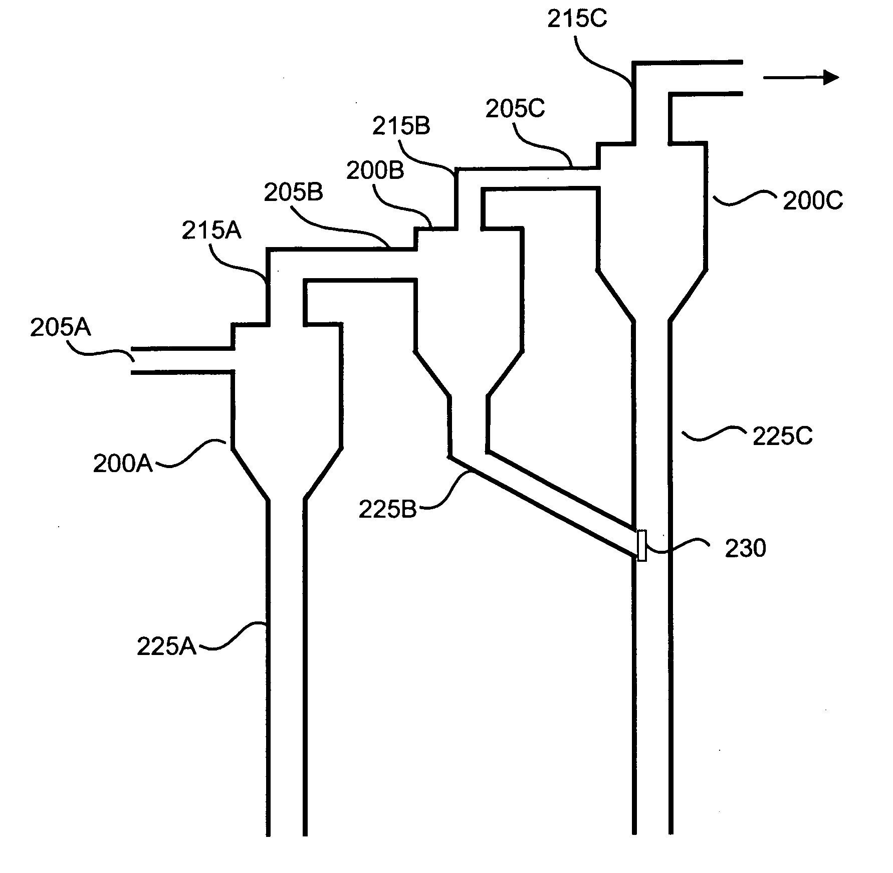
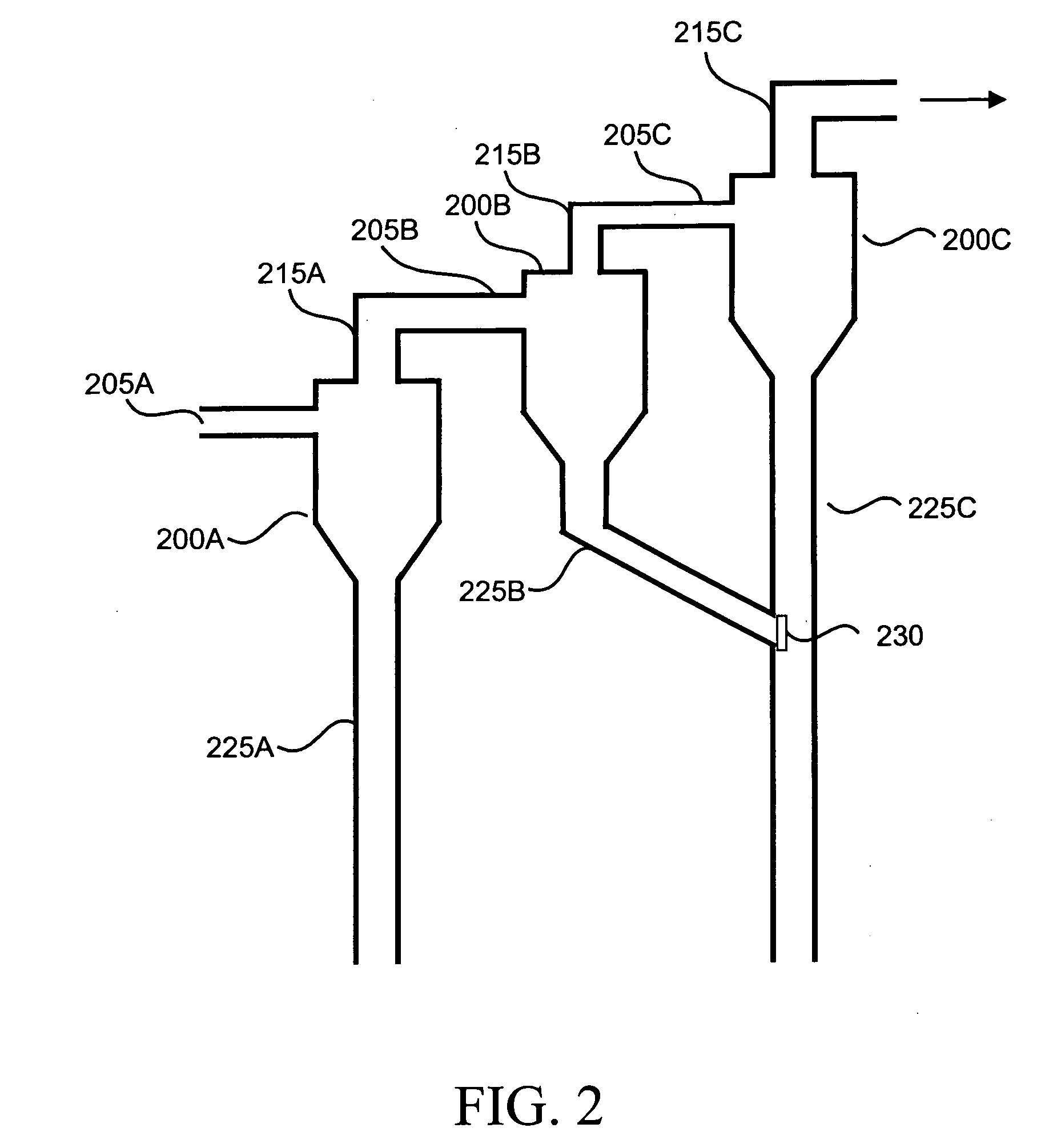
[0008] The invention provides a method and apparatus for improving the separation of solid particles from gas-solids flows. In an embodiment, this is achieved by an apparatus comprising a plurality of separator stages arranged in series, wherein each separator stage has an input conduit, a high density output conduit, and a low density output conduit. The separator stages are connected so that the output from the low density output conduit of an earlier separator stage is fed into the input conduit of a subsequent separator stage. Additionally, the high density output conduit of the earlier separator stage is merged with the high density output conduit of the subsequent separator stage. Preferably, a flapper valve or another type

Problems solved by technology

Additionally, in reaction systems that use small particle catalysts, the loss of catalyst particles during operation means that additional catalyst has to be added during operation to make up for the catalyst loss.
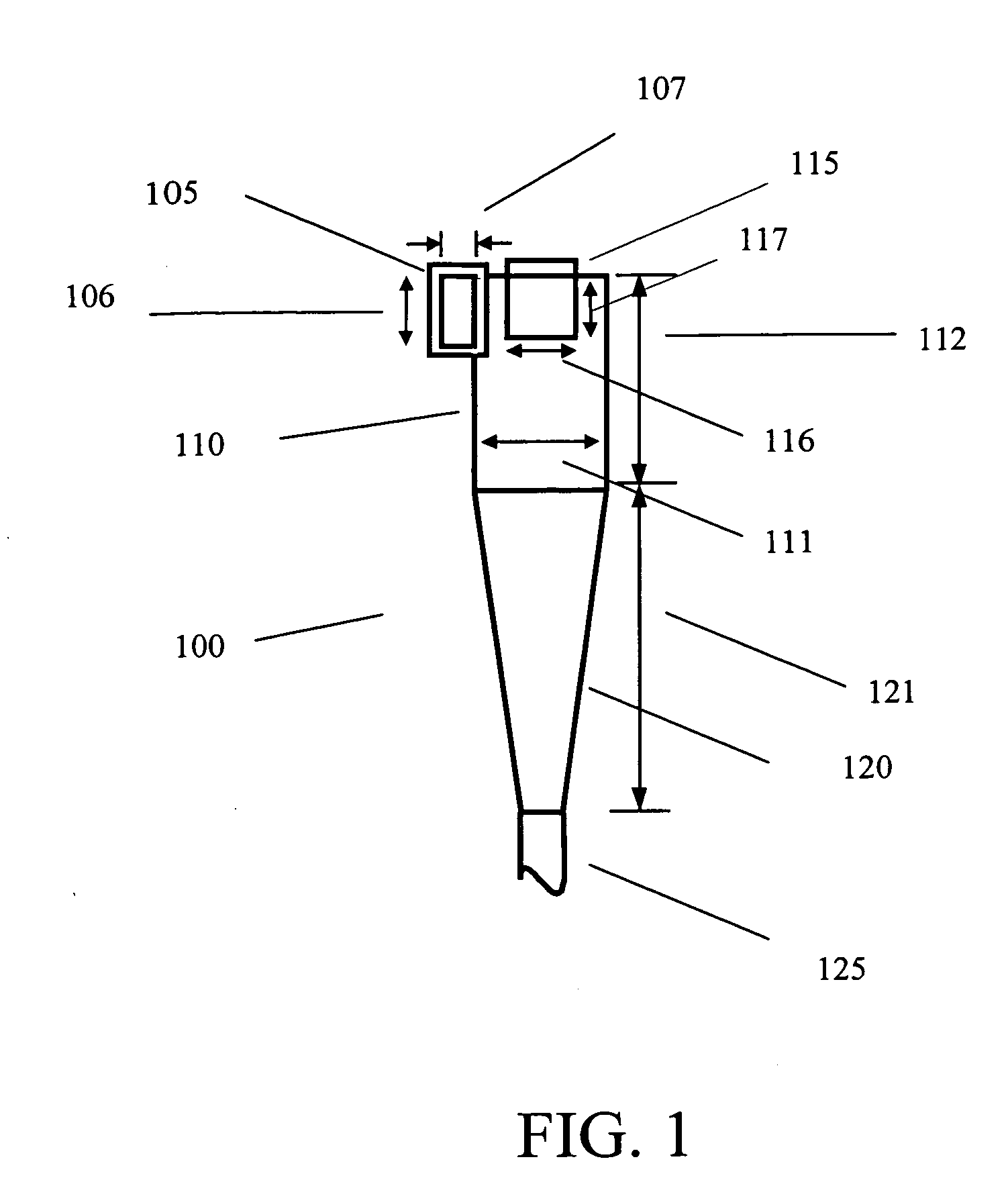
Although the cyclone separators can be arranged in stages to improve efficiency, in practice the number of stages is limited by constraints on the input and output flows of the cyclones.
Once the majority of solids have been removed from a gas flow, the remaining solids in the flow may not be sufficient to allow a conventional cyclone separator to operate at full efficiency.
In particular, it is difficult to design a multistage cyclone separator, as the amount of solids in the input flow for any cyclone stages after the first cyclone stage is often too low for fully efficient operation of a conventional cyclone.
At such a dipleg diameter, the dipleg is prone to catalyst bridging or compaction.
Catalyst bridging and / or compaction prevents outflow of catalyst from the cyclone stage and therefore causes poor separation efficiency.
However, if a larger dipleg diameter is used, the low rate of solid catalyst flow may not be sufficient to seal the dipleg.
If the dipleg does not seal properly, gas can flow back into the cyclone through the dipleg, which also reduces the separation efficiency.

Method used


Image

  • Gas-solids separation device and method
  • Gas-solids separation device and method
  • Gas-solids separation device and method

Examples


Embodiment Construction

I. Overview

[0014] This invention provides a method and apparatus for removing solids particles from a gas-solids reaction system. In particular, the process and apparatus of the invention provide improved solid particle recovery via a novel configuration and method for operating sequential cyclone separator stages.

[0015] In an embodiment, the invention provides a multistage cyclone separator, where the dipleg output flows of two or more cyclones are merged together into a single output flow. This single output flow then continues to the dust pot, particle bed, or any other part of a reaction system suitable for receiving an output flow of solid particles from a cyclone separator. Combining the dipleg output flows of two or more cyclones into a single output flow allows multiple cyclone stages to operate with high efficiency when the input flows of one or more the stages have a relatively low solids content. This embodiment also reduces the likelihood of a dipleg becoming plugged or...


PUM

PropertyMeasurementUnit
Diameteraaaaaaaaaa
Diameteraaaaaaaaaa
Diameteraaaaaaaaaa

Abstract

A multi-stage gas-solids separator is configured so that the higher density (solids) output flows of two or more of the separator stages are merged together. The multi-stage separator is preferably composed of cyclone separators, with the diplegs of at least two of the cyclone separator stages merged together.

Description

CROSS REFERENCE TO RELATED APPLICATIONS [0001] This application claims the benefit of Provisional Application No. 60 / 639,067 filed Dec. 22, 2004, the disclosure of which is fully incorporated herein by reference.FIELD OF THE INVENTION [0002] This invention is directed to an apparatus and method for separating solid catalyst particles from a gas-solids flow. BACKGROUND OF THE INVENTION [0003] Fluid-solid reaction systems, such as gas-solids reaction systems, often require the solids to be retained in early stages of the reaction system while the vapor product, essentially free of solids, is processed in downstream equipment. It is desirable in these systems that the solids be as completely removed as possible from the vapor before transferring the vapor to the downstream equipment. High solids retention in the early stages of the reaction system is desirable in cases in which the solids may contaminate the vapor product or downstream vapor process handling systems, and / or increase th...

Claims


Application Information

Patent Timeline
IPC IPC(8): B01D45/12
CPCB01D45/16B04C5/081B04C5/26F23J15/027
Inventor SMITH, JEFFREY S.BEECH, JAMES H. JR.COUTE, NICOLAS P.GOELLNER, JESSE F.CLEM, KENNETH RAY
Owner EXXONMOBIL CHEM PAT INC
Learn More