
Valve assembly

a valve assembly and valve body technology, applied in the direction of braking systems, couplings, machines/engines, etc., can solve the problems of inability to protect a hydraulic system from over-pressurization, bursting disks must be replaced, and a number of limitations

Inactive Publication Date: 2006-06-15
EATON INTELLIGENT POWER LIMITED
View PDF12 Cites 1 Cited by
  • Summary
  • Abstract
  • Description
  • Claims
  • Application Information

AI Technical Summary

Benefits of technology

[0006] A valve assembly is provided that includes a body having a bore and a longitudinal axis. A valve is received within the bore and is configured for axial movement between an open position in which fluid flow through the body is permitted and a closed position in which fluid flow through the body is prevented. First and second sealing members are secured for movement with the valve and are positioned between the valve and the body such that an internal fluid pressure within the bore is applied to a first side of the first and second sealing members and a common reference pressure is applied to a second side of the first and second sealing members. A first surface area portion of the bore adjacent the first sealing member is greater than a second surface area portion of the bore adjacent second sealing member such that an axial force imparted on the valve adjacent the second sealing member is less than an axial force imparted on the valve adjacent the first sealing member. A resiliently compressible member is positioned to bias the valve toward the open position. The valve is normally in the open position and is moved to the closed position when the internal fluid pressure exceeds a predetermined pressure. The valve is adapted to return to the open position when the internal fluid pressure is substantially less than the predetermined pressure.

Problems solved by technology

While hydraulic fuses adequately protect a hydraulic system from fluid loss, they are generally incapable of protecting a hydraulic system from over-pressurization.
While these devices effectively vent pressurized fluid when a hydraulic system or subsystem is over-pressurized, they exhibit a number of limitations.
Among other limitations, burst disks must be replaced once they are ruptured.
Additionally, unlike in-line hydraulic fuses, burst disks require additional plumbing for discharging pressurized fluid.
Another limitation of burst disks is that they expose a downstream portion of the hydraulic system to a momentary high-pressure impulse prior to and during rupture.
Moreover, burst disks have a tendency to fail due to low-pressure cycling fatigue.
Another limitation of pressure relief valves is that they are relatively large in size and weight, rendering them unsatisfactory for use in hydraulic systems where size and weight must be minimized.

Method used


Image

  • Valve assembly
  • Valve assembly
  • Valve assembly

Examples


Embodiment Construction

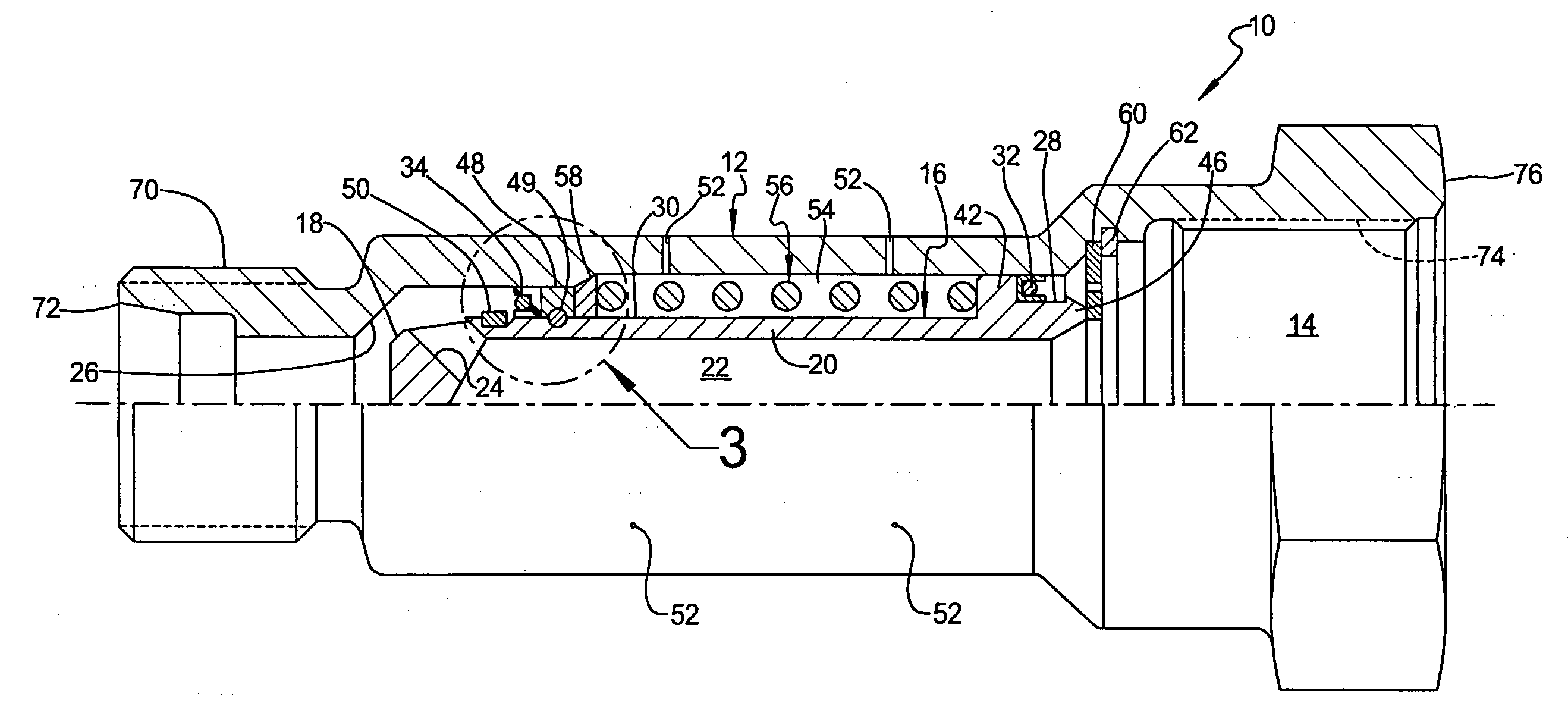
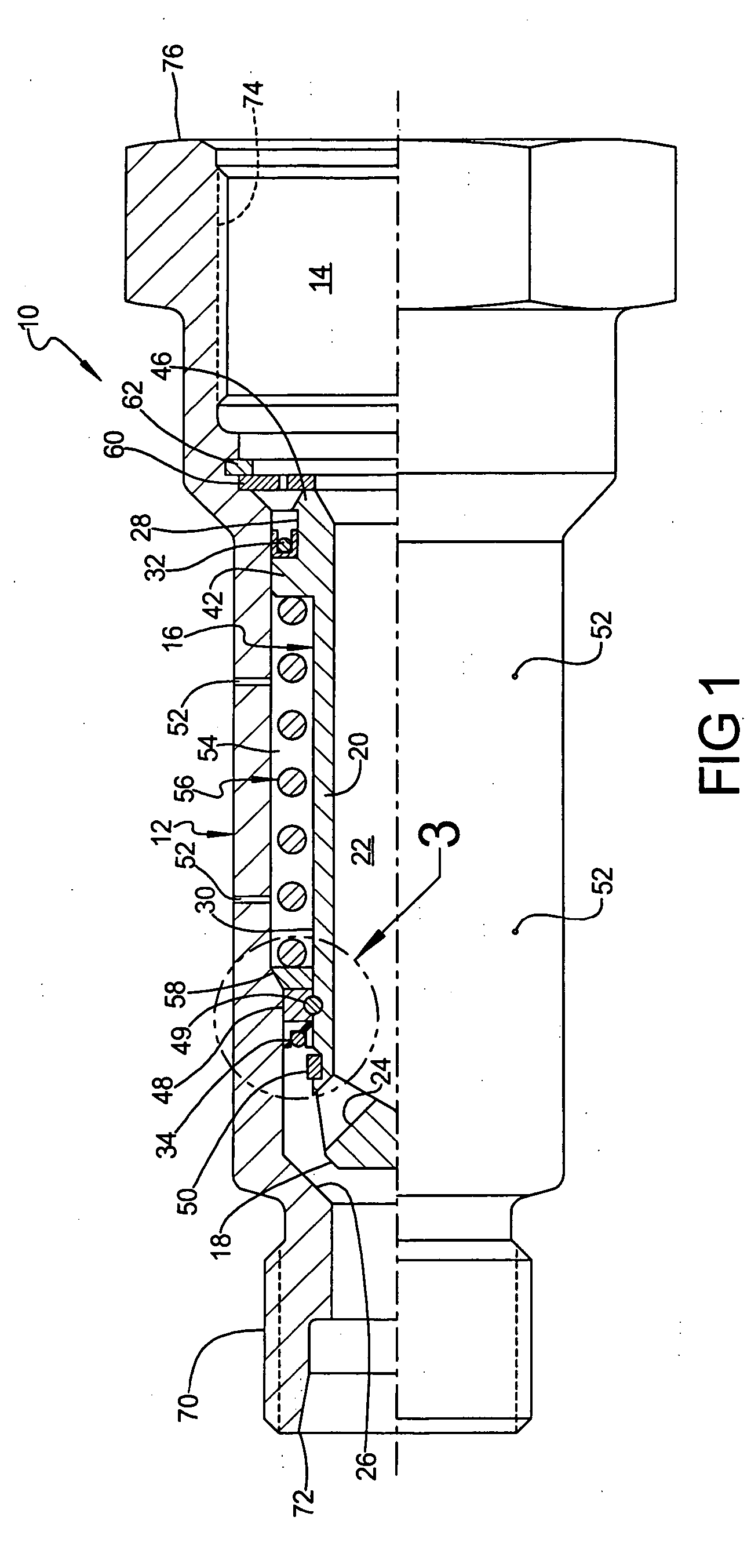
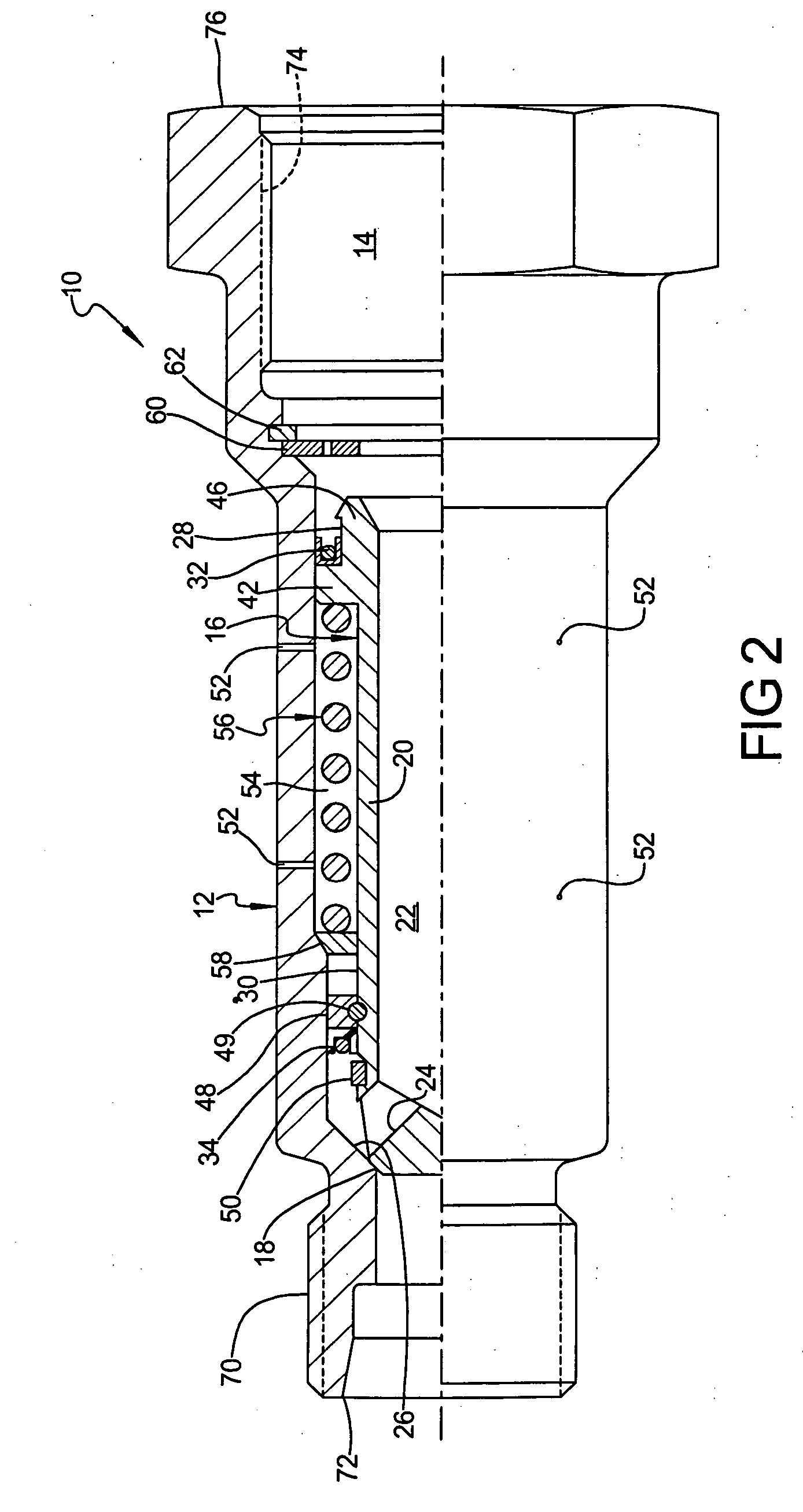
[0018]FIGS. 1 and 2 illustrate a partial cross-sectional view of a valve assembly 10 shown in accordance with an embodiment of the present invention. In the illustrated embodiment, valve assembly 10 includes a body 12 having a bore 14 and a longitudinal axis A-A. A valve 16 is received within the bore 14 and is configured for axial movement between an open position (e.g., FIG. 1) in which fluid flow through the body 12 is permitted and a closed position (e.g., FIG. 2) in which fluid flow through the body 12 is prevented.

[0019] In an embodiment, valve 16 is generally cylindrical and includes a head portion 18 and an elongated stem portion 20 that includes a fluid flow passage 22 extending therethrough. At least one channel 24 extends through head portion 18 to provide fluid flow passage 22 in communication with the portion of bore 14 that is downstream of valve 16 when valve 16 is in the open position. Head portion 18 is adapted to engage an inner surface 26 of bore 14 downstream of...


PUM


Abstract

A valve assembly includes a body having a bore and a valve received within the bore for movement between an open position and a closed position. First and second sealing members are secured for movement with the valve and are positioned between the valve and the body such that an internal fluid pressure within the bore is applied to a first side of the sealing members and a common reference pressure is applied to a second side. An axial force imparted on the valve adjacent the second sealing member is less than an axial force imparted on the valve adjacent the first sealing member. A resiliently compressible member is positioned to bias the valve toward the normally open position. The valve is moved to the closed position when the internal fluid pressure exceeds a predetermined pressure and returns to the open position when the internal fluid pressure is substantially less than the predetermined pressure.

Description

FIELD OF THE INVENTION [0001] The present invention relates generally to valve assemblies for hydraulic systems and, more particularly, to an over-pressure protection valve assembly for use in a hydraulic system. BACKGROUND OF THE INVENTION [0002] Devices for monitoring fluid flow and pressure in a hydraulic system and responding to pressure and flow transients that immediately follow a ruptured hydraulic line, hose or hydraulic device leak, so-called “hydraulic fuses,” are known in the art. Hydraulic fuses are typically in-line valves that protect a hydraulic system or subsystem by sensing increased flow through the valve, resulting from a rupture line or leak, and closing the valve to block fluid flow upstream of the rupture to prevent further spillage. [0003] While hydraulic fuses adequately protect a hydraulic system from fluid loss, they are generally incapable of protecting a hydraulic system from over-pressurization. To prevent over-pressurization, hydraulic systems or subsys...

Claims


Application Information

Patent Timeline
Patent Type & Authority Applications(United States)
IPC IPC(8): G05D16/06
CPCF16K17/30Y10T137/7808Y10T137/7835
Inventor FLYNN, WILLIAM THOMAS
Owner EATON INTELLIGENT POWER LIMITED
Learn More