
Hair clip

a technology of hair clips and clips, applied in the field of hair clips, can solve the problems of fragile, fragile, and easy to fail to use, and the spring and pivot mechanism is not very aesthetically appealing, and the cover mechanism is complex to build and be damaged

Inactive Publication Date: 2006-06-15
LINSHELL HLDG LTD
View PDF21 Cites 16 Cited by
  • Summary
  • Abstract
  • Description
  • Claims
  • Application Information

AI Technical Summary

Benefits of technology

[0007] By laterally spacing the pivot axes it is possible to use a body which can be decorated or made less visible and can also act to hide the pivot mechanisms if necessary, thereby improving the aesthetic appearance of the clip in use.
[0014] In another embodiment the body is formed of thin section edge regions defining a central aperture through the body between the pivot axes. Thus in this embodiment the hair of the wearer can be seen through the body thus reducing the visibility of the clip.
[0019] Another aspect of the present invention provides a hair clip comprising a body portion; jaw portions attached to said body portion; and a jaw opening arrangement to allow said jaw portions to be opened single handed; said jaw portions having tines and being hingedly and resiliently connected to said body portion to urge said tines together for gripping hair, wherein said jaw portions are connected to said body portion at hinge positions defining laterally spaced axes, and said body portion has thin section edge portions defining a large aperture between said axes, to allow hair of a wearer to be seen therethrough when worn.

Problems solved by technology

The problem is that although these clips are easy to use single handed, the spring and pivot mechanism is not very aesthetically appealing.
Thus the cover mechanism is complex to build and is fragile and thus liable to failure in use, especially as the clip ages.
This operation requires the use of two hands and is thus more complex than that required for opening butterfly clips.
This limits the decorative ability of the central region.
This device is however bulky as a hair clip and has low aesthetic appeal.

Method used


Image

  • Hair clip
  • Hair clip
  • Hair clip

Examples


first embodiment

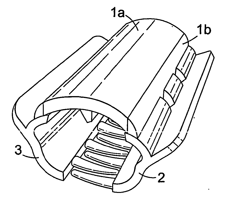
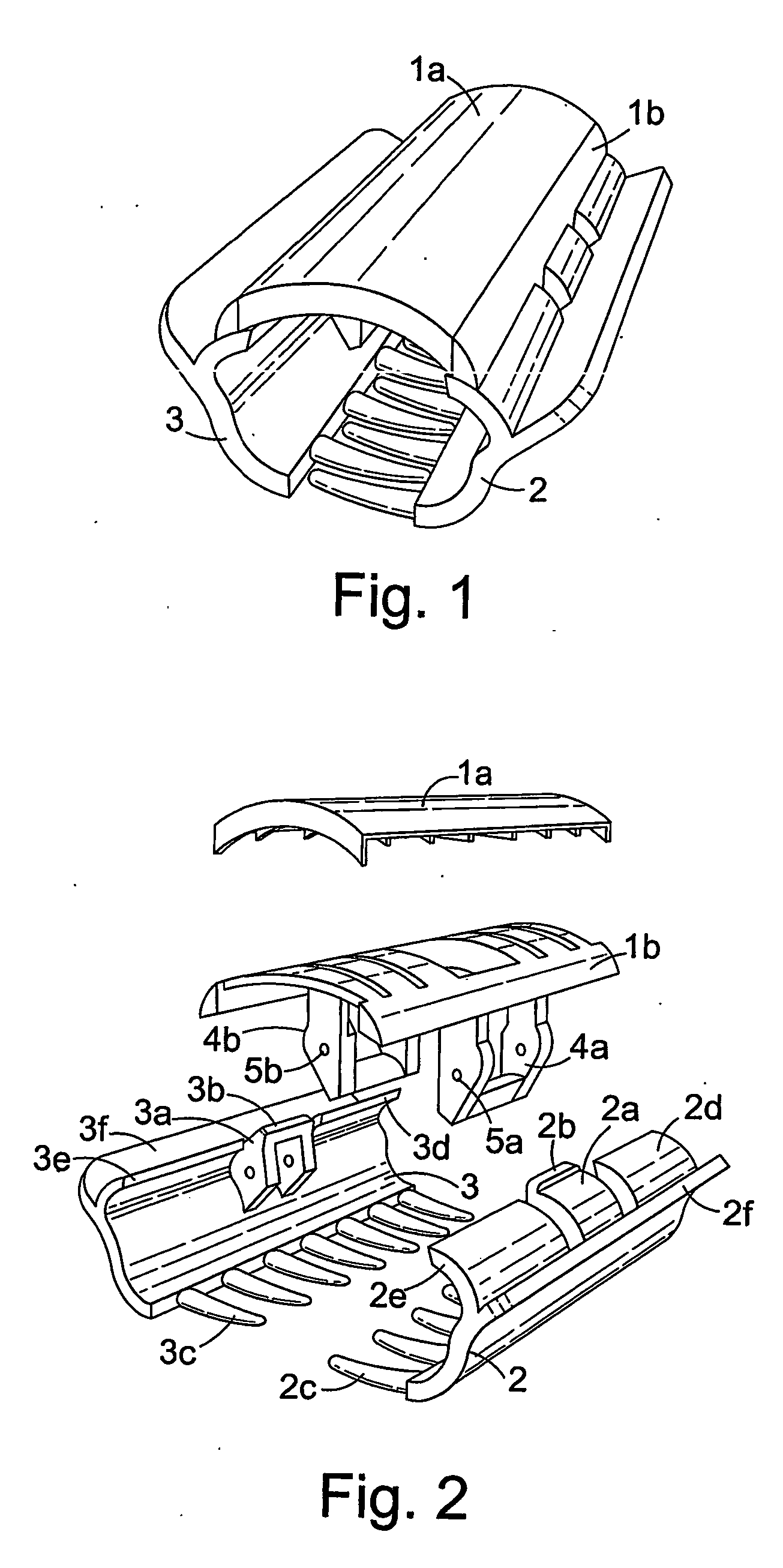
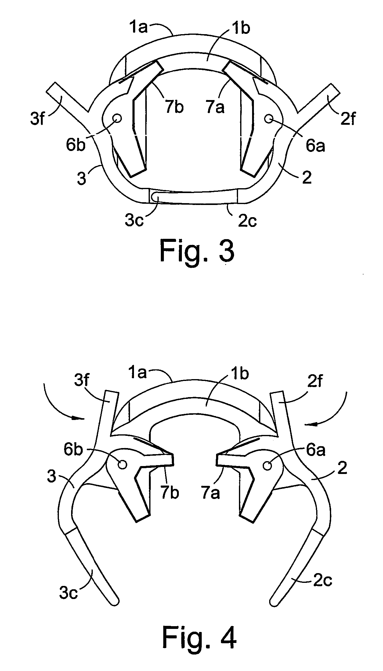
[0037] the present invention will now be described with reference to FIGS. 1 to 4.

[0038] The hair clip of this embodiment comprises a body 1 formed of a base 1a and a cover 1b which is coupled to the base 1a. The decorative cover can either be detachable in use to enable the cover to be changed, or it can only be fixed. The fixed cover enables the fixing of different covers to the same base 1a during the manufacturing process. The base 1a has an elongate arcuate carrying surface for carrying the decorative cover 1b in an elongate arcuate shape. Below the carrying surface there are provided two arms 4a and 4b extending away from the base 1a at spaced positions to the sides of the base 1a. The arms 4a and 4b have pivot holes 5a and 5b for receiving pivot pins 6a and 6b.

[0039] Two opposed elongate jaws 2 and 3 have a curved or roughly arcuate cross section. A pivot arm 2a and 3a respectively extends inwardly from an upper edge of each jaw 2 and 3 and has a pivot hole for receiving the...

second embodiment

[0042] the present invention will now be described with reference to FIGS. 5 to 10. This embodiment is similar to the first embodiment except that the jaw opening arrangement is different.

[0043] The hair clip of this embodiment comprises a body 10 having an elongate arcuate decorative outer surface. Below the decorative surface there are provided two arms 10a and 10b extending away from the body 10 at spaced positions to the sides of the body 10. The arms 10a and 10b have pivot holes for receiving pivot pins 15a and 15b.

[0044] Two opposed elongate jaws 11 and 12 have a curved or roughly arcuate cross section. A pivot arm 11a and 12a respectively extends inwardly from an upper edge of each jaw 11 and 12 and has a pivot hole for receiving the respective pivot pin 15a and 15b. In this way the jaws 11 and 12 are mounted on the body 10 to pivot about pivot axes spaced from one another. Along one edge of the jaws 11 and 12 away from the pivot arms 11a and 12a respectively tines 11c and 1...

fifth embodiment

[0056] the present invention will now be described with reference to FIG. 13. This embodiment is similar to the fourth embodiment except that the pivotable mounting of the jaws on the body is formed by regions or resilient material interconnecting the jaws and the body.

[0057] The hair clip of this embodiment comprises a body 30 having an elongate arcuate carrying surface. Either side, along the elongate edges of the body 30 the body is connected to two jaws 31 and 32. The connection is formed by regions of resilient material 33 and 34 between the jaws 31 and 32 and the body 30. This forms a hinge or pivot point extending along the edges of the body 30. Thus the body 30 and the jaws 31 and 32 are formed in three pieces and joined by connection of a resilient section of material 33 and 34.

[0058] The jaws 31 and 32 are provided with handle portions 31a and 32a to enable to one handed operation of the hair clip. Also the jaws 31 and 32 have tines 31b and 32b for gripping hair.

[0059] T...


PUM


Abstract

A hair clip comprises a body, jaws mounted on the body and a jaw opening arrangement to allow the jaws to be opened single handed. The jaws have tines and are mounted at spaced positions on the body so as to be pivotable at the positions to resiliently grip hair in the tines. The spacing of the pivot positions on the body enables a body to be used which can be decorated or hollow to enhance the aesthetics of the hair clip.

Description

FIELD OF THE INVENTION [0001] The present invention generally relates to hair clips and more particularly to hair clips having pivotable jaws for gripping hair. BACKGROUND OF THE INVENTION [0002] One type of prior art clips which use pivotable jaws are generally known as butterfly clips. These clips comprise two jaw members having tines and being joined along a pivot axis. A spring arrangement is provided at the pivot axis to resiliently urge the tines of the jaws to a closed position to grip the hair. To enable the tines to be disengaged and the jaws opened, the jaws are provided with lever members extending therefrom at a position away from the tines. This gives the clip the classic ‘butterfly’ appearance and hence its common name. When the clips are worn the primary visible parts are the lever members or ‘wings’ and the joining pivot and spring mechanism. The problem is that although these clips are easy to use single handed, the spring and pivot mechanism is not very aesthetical...

Claims


Application Information

Patent Timeline
Patent Type & Authority Applications(United States)
IPC IPC(8): A45D8/20A45D8/00
CPCA45D8/20A45D2008/006A45D8/006
Inventor SALISBURY, SHELLEY-ANNEWALKER, LINDSEY J.
Owner LINSHELL HLDG LTD
Learn More