
Dust collecting unit of vacuum cleaner

Inactive Publication Date: 2006-06-15
LG ELECTRONICS INC
View PDF2 Cites 50 Cited by
  • Summary
  • Abstract
  • Description
  • Claims
  • Application Information

AI Technical Summary

Benefits of technology

[0012] An object of the present invention is to provide a dust collecting unit of a vacuum cleaner, which is designed to increase the density of collected foreign substances.
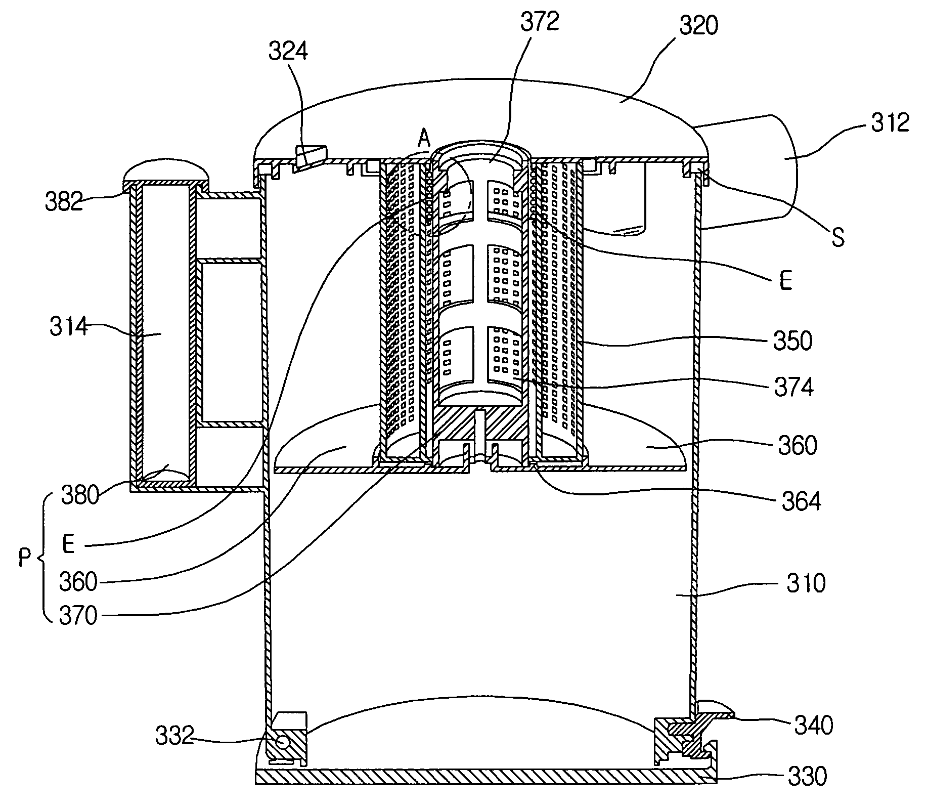
[0013] Another object of the present invention is to provide a dust collecting unit of a vacuum cleaner, which is designed to compress collected foreign substances at a preset position in the dust collecting unit to clearly remove the collected foreign substances, prevent generation of dust when the collected foreign substances are removed, and prevent the collected foreign substance from spreading in the dust collecting unit.
[0019] According to the present invention, the inner space of the dust collecting unit can be efficiently used by compressing the collected foreign substances. Therefore users can conveniently use the vacuum cleaner. Particularly, dust does not generate when the collected foreign substances are removed from the dust collecting unit, and the removing of the collected foreign substances from the dust collecting unit can be done less frequently but more easily.

Problems solved by technology

This low density of the accumulated foreign substances causes the following problems.
Since the limited space of a dust collection container of the dust collecting unit is easily filled up by the loosely accumulated foreign substances, the dust collection container should be emptied frequently, thereby causing inconvenience to users.
If the dust collection container is not emptied periodically, the build up of the foreign substances disturbs the airflow and thereby lowers the collecting efficiency of the dust collecting unit.
Further, dust generates from the loosely accumulated foreign substances during the cleaning of the dust collection container.
This causes health-related problems and makes the cleaning of the dust collection container more difficult.
Furthermore, when the collected foreign substances are spread throughout the dust collection container, the outer appearance becomes bad to give an unpleasant feeling to the user.

Method used


Image

  • Dust collecting unit of vacuum cleaner
  • Dust collecting unit of vacuum cleaner
  • Dust collecting unit of vacuum cleaner

Examples


Embodiment Construction

[0026] Reference will now be made in detail to the preferred embodiments of the present invention, examples of which are illustrated in the accompanying drawings.

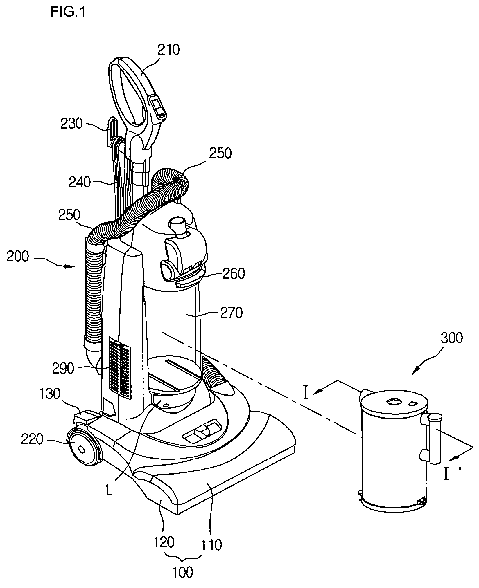
[0027]FIG. 1 is a perspective view of an upright vacuum cleaner according to an embodiment of the present invention.

[0028] Referring to FIG. 1, the upright type vacuum cleaner includes a suction nozzle unit 100 sucking air containing foreign substances such as dust and dirt while moving along a floor, a main body 200 in which suction power generating components such as a motor and a fan are installed to suck the air, and an operating unit 210 mounted on a top of the main body 200 so that a user grasps the operating unit 210 in use.

[0029] Hereinafter, each component of the vacuum cleaner will be more fully described.

[0030] The suction nozzle unit 100, which is designed to suck the air, includes a nozzle upper cover 110 and a nozzle lower cover 120 that form the upper and lower outsides of the suction nozzle unit 100, res...


PUM

PropertyMeasurementUnit
Forceaaaaaaaaaa
Shapeaaaaaaaaaa

Abstract

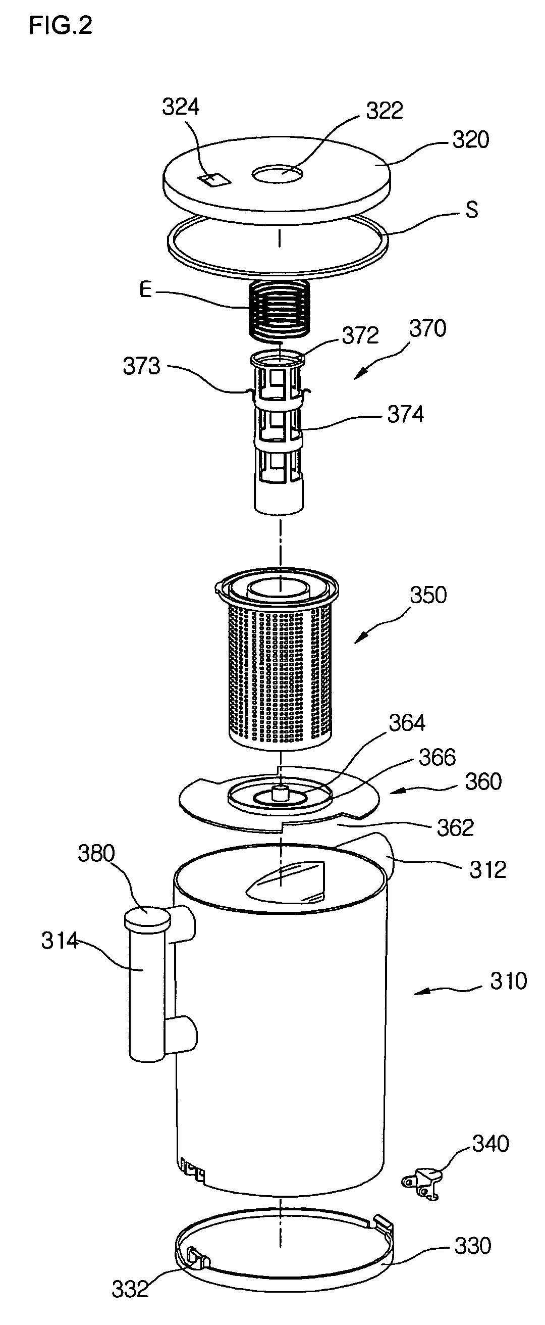
There is provided a dust collecting unit of a vacuum cleaner, the dust collecting unit being designed to increase the density of foreign substances collected in a dust collection container. In the dust collecting unit, a dust collection container collects foreign substances, a top cover closes a top of the dust collection container, a bottom cover closes a bottom of the dust collection container, a compartment plate divides an inner space of the dust collection container into a foreign substance separating compartment and a foreign substance storing compartment, and a bar pushes the compartment plate to the foreign substance storing compartment to compress the foreign substances stored in the foreign substance storing compartment.

Description

BACKGROUND OF THE INVENTION [0001] 1. Field of the Invention [0002] The present invention relates to a vacuum cleaner, and more particularly, to a dust collecting unit that is installed to a vacuum cleaner to collect foreign substances such as dust and dirt. The present invention further relates to a dust collecting unit of a vacuum cleaner, in which collected foreign substances are compressed to reduce cleaning frequency of the collecting unit and prevent user's discomfort caused by the dust generating when the collected foreign substances are removed. [0003] 2. Description of the Related Art [0004] A typical vacuum cleaner includes a suction nozzle unit to suck air containing foreign substances such as dust and dirt while the suction nozzle unit moves along a floor, a main body in which a motor and a fan are installed to generate air suctioning force through the suction nozzle unit, a dust collecting unit detachably installed to the main body to filter out the foreign substances, ...

Claims


Application Information

Patent Timeline
IPC IPC(8): B01D47/00
CPCA47L9/108A47L9/1666Y10S55/03A47L9/10
Inventor PARK, TAE JIN
Owner LG ELECTRONICS INC
Learn More