
Ringed forceps

a technology of ringed forceps and ringed ringed fingers, which is applied in the direction of surgical forceps, surgical staples, catheters, etc., can solve the problems of inability to achieve efficacy, difficulty in controlling, and injuring patients, so as to promote tissue sticking together and minimize heat energy loss

Inactive Publication Date: 2006-06-08
THE TRUSTEES OF COLUMBIA UNIV IN THE CITY OF NEW YORK
View PDF8 Cites 26 Cited by
  • Summary
  • Abstract
  • Description
  • Claims
  • Application Information

AI Technical Summary

Benefits of technology

[0029] It is another object of the present invention to provide an portable instrument which does not require an external power source.
[0062] There is no instrument or method in the prior art which specifically seeks to obtain surgical coagulation, sealing, joining or cutting by a combination of resistant heat energy and pressure at a time, temperature and pressure which together are sufficient but not excessive to produce protein denaturization, and with a physical configuration and materials of construction which promote the sticking together of the tissues being treated while minimizing losses of heat energy to surrounding tissues beyond the treatment zone.

Problems solved by technology

One of the best ways to denature a protein is to heat it up to a temperature high enough to cause the intra-molecular hydrogen bonds to break, but which is not high enough to break the much stronger peptide-peptide covalent bonds along the main chain.
The problem with this approach is not efficacy, it is control and containment of the amount and extent of tissue which is cauterized or injured.
This high frequency falls in the range of the AM radio band, which is the reason why many electrical instruments such as monitors used in the OR will register interference when electrocautery is activated.
There are many potential problems stemming from the use of such high frequencies, including difficulty in controlling stray currents which can injure patients and interfere with pacemakers and computer equipment.
This instrument would certainly not be suitable for use in laparoscopic or open surgery in which large amounts tissue must be not only coagulated but also divided.

Method used


Image

  • Ringed forceps
  • Ringed forceps
  • Ringed forceps

Examples


Embodiment Construction

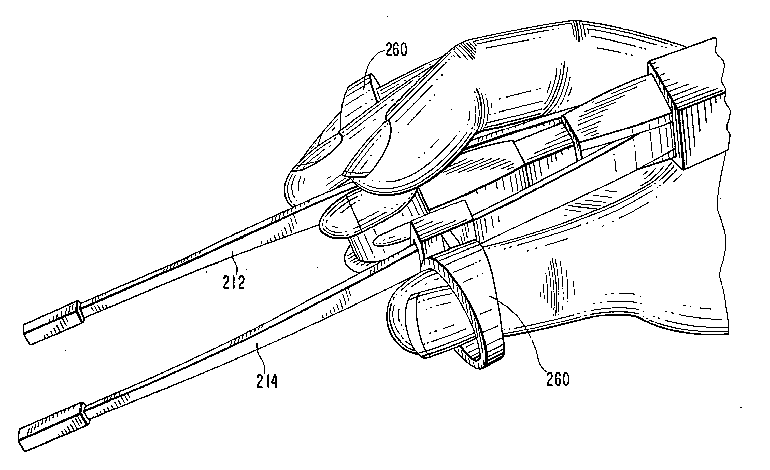
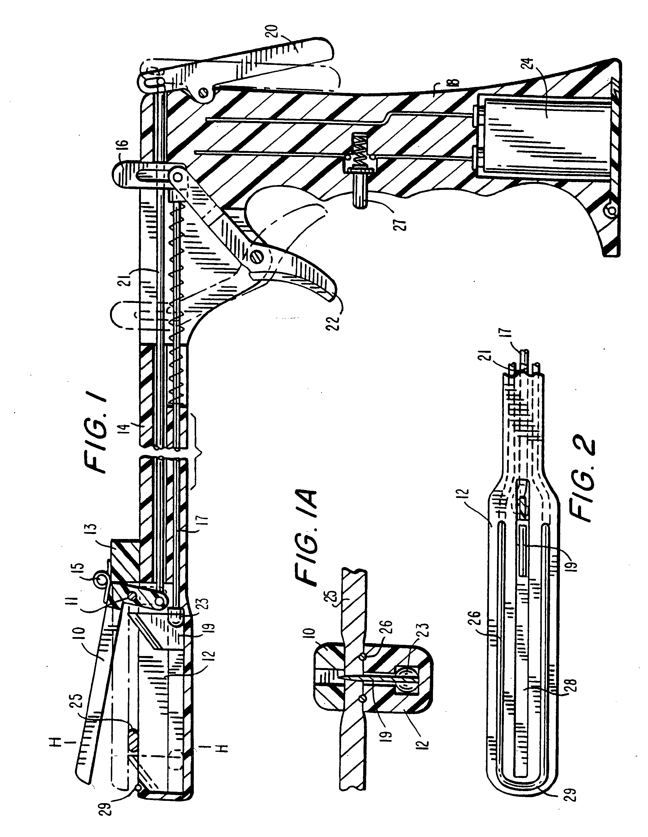
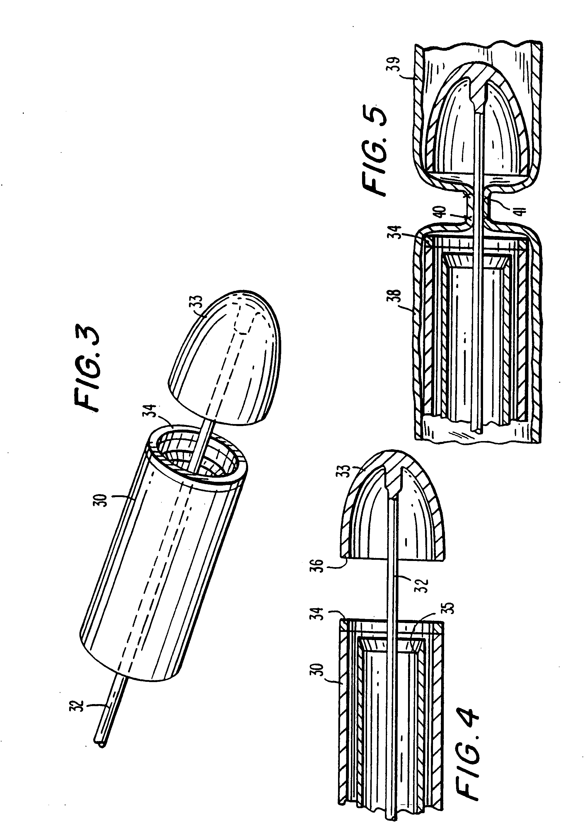
[0088] The invention can perhaps be better appreciated from the drawings. FIG. 1 depicts a schematic representation of the instrument of the invention showing an upper jaw 10, a lower jaw 12, an elongated shaft 14 attached to a handle 18, having a lever 20 for opening and closing the jaws. Upper jaw 10 is attached at hinge 11 to spring support member 13, and spring 15 is attached to both upper jaw 10 and spring support member 13 to bias upper jaw 10. Lever 20 is operatively connected through rod 21 to one or both of upper jaw 10 and lower jaw 12. The end of shaft 14 closest to handle 18 is provided with (1) a pusher 6 which is operatively connected through member 17 and connector 23 to a cutting knife blade 19 housed in lower jaw 12 and (2) a trigger 22 to actuate pusher 6 which in turn actuates cutting blade 19. The lower end of handle 18 is provided with a rechargeable battery pack 24, which is operatively connected to heating element actuator 27 and heating wire element 26 in low...


PUM

PropertyMeasurementUnit
temperatureaaaaaaaaaa
temperaturesaaaaaaaaaa

Abstract

A surgical instrument comprises two oppositely-positioned working numbers each having proximal and distal ends and each having a working surface. The instrument also comprises at least one ring member affixed to a least one of the working members to encompass one or more of a user's fingers. In one embodiment at least one working surface has a heating element to cut or seal and cut tissue.

Description

CROSS-REFERENCE TO RELATED APPLICATIONS [0001] This application is a continuation of co-pending U.S. patent application Ser. No. 10 / 266,497, filed Oct. 8, 2002, which is in turn a continuation-in-part of co-pending U.S. patent application Ser. No. 09 / 374,483, filed Aug. 13, 1999, which in turn is a continuation-in-part of U.S. patent application Ser. No. 09 / 035,691, filed Mar. 5, 1998, which is based upon U.S. provisional patent application Ser. No. 60 / 038,589, filed Mar. 5, 1997, all of which are incorporated herein by reference.FIELD OF THE INVENTION [0002] The present invention relates generally to instruments and methods for sealing and joining or cutting tissue. The instruments of the present invention are especially intended for use during either conventional open surgery or endoscopic or laparoscopic surgery and have finger-constraining members to encompass at least one of the user's fingers. BACKGROUND OF THE INVENTION [0003] Hemostasis, or blood clotting, can be obtained by...

Claims


Application Information

Patent Timeline
Patent Type & Authority Applications(United States)
IPC IPC(8): A61B18/04A61B17/00A61B17/072A61B17/125A61B17/32A61B18/08A61B18/14A61B18/20A61F7/00B32B27/08
CPCA61B10/02A61B17/072A61B17/32A61B17/320068A61B18/085A61B18/1445A61B18/20A61B2017/00734A61B2017/07214A61B2018/00083A61B2018/00095A61B2018/0022A61B2018/00595A61B2018/00601A61B2018/0063A61B2018/00666A61B2018/00684A61B2018/00761A61B2018/00886A61B2018/0091A61B2018/1462A61B2018/1861A61B2019/464A61F2007/0078B32B27/08A61B2090/064Y10T428/31544Y10T428/249985Y10T428/249981Y10T428/249984A61B2017/320069A61B2017/32007A61B2017/320071
Inventor TREAT, MICHAEL R.
Owner THE TRUSTEES OF COLUMBIA UNIV IN THE CITY OF NEW YORK
Learn More