
Methods and systems for electric power sub-metering

a sub-metering and power supply technology, applied in the direction of measuring devices, coupling device connections, instruments, etc., can solve the problem of limited distribution of electricity to an individual customer

Active Publication Date: 2006-06-08
ABB (SCHWEIZ) AG
View PDF8 Cites 39 Cited by
  • Summary
  • Abstract
  • Description
  • Claims
  • Application Information

AI Technical Summary

Benefits of technology

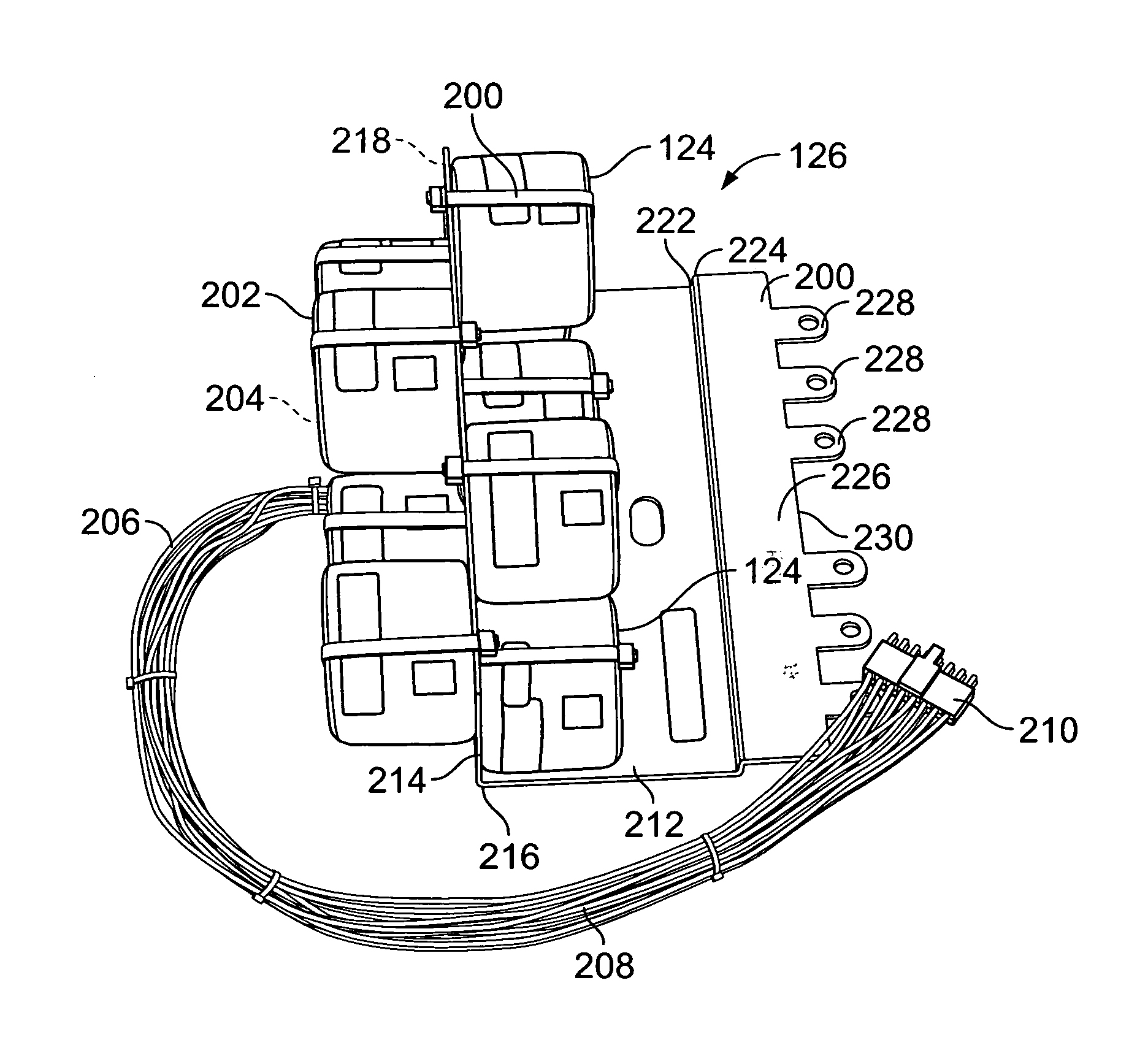
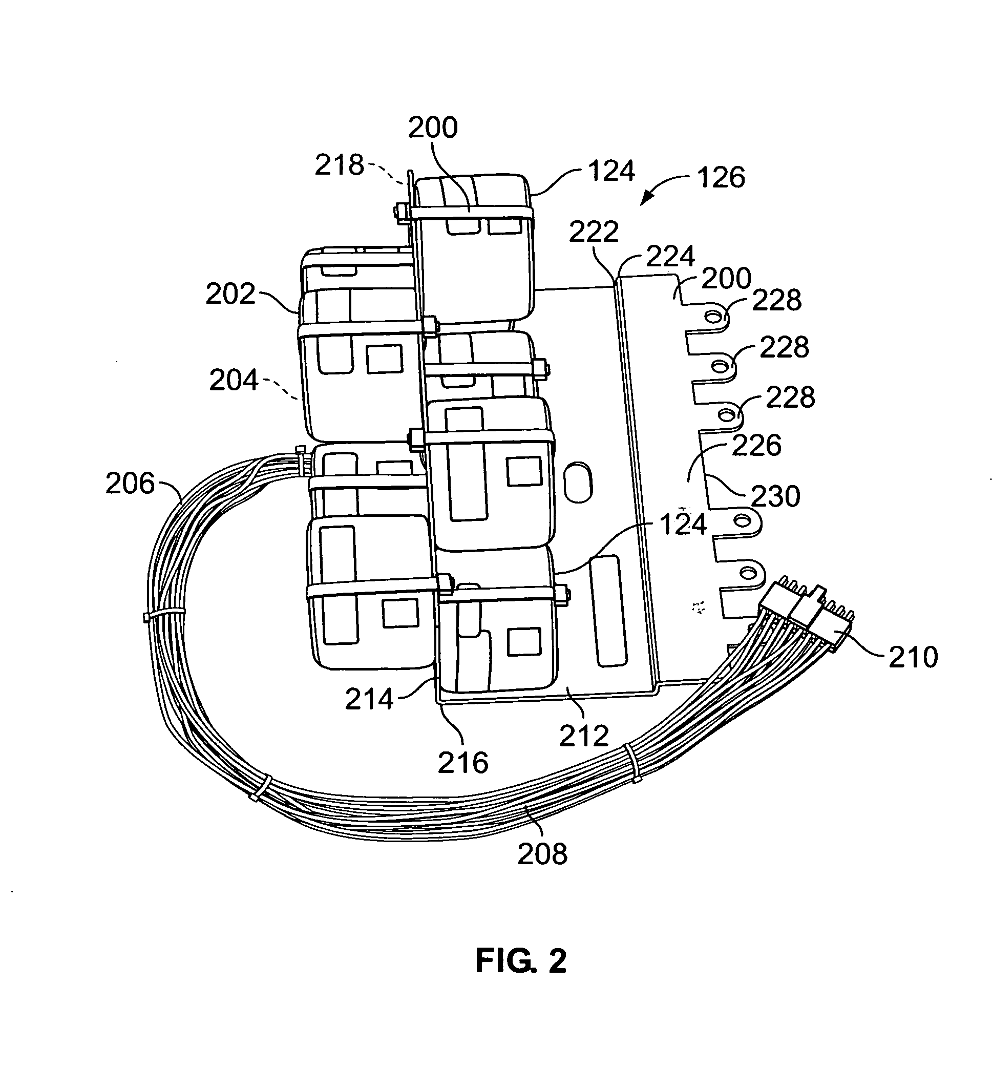
[0004] In another aspect, a load sensing assembly is provided. The assembly includes a plurality of load sensors configured to be communicatively coupled to respective load carrying branch circuit conductors, the plurality of load sensors configured to generate a load signal proportional to the load carried in the respective branch circuit conductors, a plurality of output leads, each output lead coupled to an output of a respective load sensor, the output leads coupled to a termination connector comprising a first shape and a plurality of pin connections, the pin connections configured to mate in one-to-one correspondence with the output leads, the first shape configured to mate to a complementary second-shaped connector, and an L-bracket comprising a poke-yoke configuration that facilitates preventing installation of the L-bracket in other than a predetermined orientation, the L-bracket configured to support the plurality of load sensors in substantial alignment with respective load carrying branch circuit conductors.

Problems solved by technology

In such areas, electricity distribution to an individual customer was limited to a regulated utility entity.

Method used


Image

  • Methods and systems for electric power sub-metering
  • Methods and systems for electric power sub-metering
  • Methods and systems for electric power sub-metering

Examples


Embodiment Construction

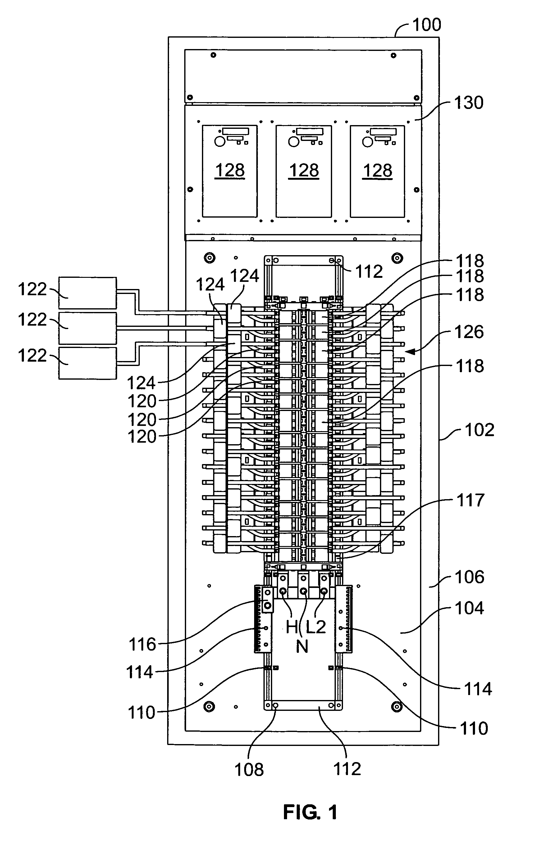
[0010]FIG. 1 is an isometric view of an exemplary distribution panel 100 with a cover (not shown) removed in accordance with an embodiment of the present invention. In the exemplary embodiment, distribution panel 100 includes a base 102 that may include one or more sidewalls extending therefrom to define an at least partially enclosed space. A backplane 104 may be coupled to an interior surface 106 of base 102. Backplane 104 may be coupled directly to surface 106 or may be separated from surface 106 by standoffs or spacers (not shown) positioned between surface 106 and backplane 104 such that a gap is defined between surface 106 and backplane 104. Distribution panel 100 further includes a channel assembly 108 mounted to surface 106 for mounting distribution panel components as described below. Channel assembly 108 includes one or more rails 110 and one or more mounting strips 112 that are used to couple channel assembly 108 to surface 106.

[0011] A termination strip 114 may be coupl...


PUM


Abstract

Methods and systems for electrical distribution submetering are provided. The electrical distribution submetering system includes a modular load sensing assembly including a plurality of load sensors. The load sensing assembly further includes a first cable having a first cable termination connector, an interface board including a plurality of electrical terminations, at least some of the terminations electrically coupled to a second cable having a second cable termination connector coupled to at least one conductor of the second cable, the second cable termination connector being complementary to the first cable termination connector such that the first cable termination connector and the second cable termination connector are configured to be electrically coupled. The submetering system also includes a modular sub metering electronics communicatively coupled to the interface board, the modular sub metering electronics configured to determine a branch circuit load in the electrical distribution system using the detected electrical load.

Description

BACKGROUND OF THE INVENTION [0001] This invention relates generally to electric distribution panels, and more particularly to methods and systems for submetering power delivered from electric distribution panels. [0002] At least some government entities, such as states are permitting and in some cases requiring the deregulation of wholesale electricity distribution. In such areas, electricity distribution to an individual customer was limited to a regulated utility entity. With new regulations in effect, a landlord, such as an apartment building owner may now purchase bulk power for the apartment building and resell the power to the individual apartment dwellers. Heretofore, the metering of power distributed to individual apartment was performed by individual demand meters owned by the regulated utility and corresponding to each apartment. A new metering scheme, to take advantage of the deregulated environment, may allow for only one utility electric demand meter per apartment build...

Claims


Application Information

Patent Timeline
IPC IPC(8): H01R9/03
CPCG01R22/06G01R22/065
Inventor CAGGIANO, ROBERT J.REDDITHA, SURESHPRABHU, RAGHUNATH T.FRITZ, DEREK WILLIAM
Owner ABB (SCHWEIZ) AG
Learn More