Single torsional hinge mirror package

a scanning engine and hinge technology, applied in the field of single torsional hinge mirror package, can solve the problems of tension or compression of the hinges, and the resonant frequency of the scanning mirror to change beyond acceptable limits, or even destroy the mirror

Inactive Publication Date: 2006-06-08
TEXAS INSTR INC
View PDF4 Cites 8 Cited by
  • Summary
  • Abstract
  • Description
  • Claims
  • Application Information

AI Technical Summary

Benefits of technology

[0011] According to one embodiment of the invention, the pivoting mirror may be a single sheet of silicon. However, it has been found advantageous to form a multilayered mirror device comprising not only a single layer mirror member, but also a hinge layer that is integral with the torsional hinge or hinges and which has a mirror side and a magnet side. The layer of material forming the mirror member has its back surface attached to the mirror side of the hinge layer, and the permanent magnet is bonded to the magnet side of the hinge layer. To help center the mass moment of the mirror device on the pivot axis, a spacer layer may be included between the mirror layer and the hinge layer. For many applications, it is also advantageous that the mirror device oscillate or pivot around its torsional hinge or hinges at a selected frequency, which selected frequency may advantageously be the resonant frequency of the device.

Problems solved by technology

Unfortunately, the resonant frequency of the mirror as it pivots about its torsional hinges is highly susceptible to stresses that cause tension or compression of the hinges.
However, distortion of the bracket itself due to mounting stresses and / or different CTE (coefficient of thermal expansion) between a mirror and the bracket can produce sufficient stress in the mirror bracket that will cause the resonant frequency of the scanning mirror to change beyond acceptable limits or even destroy the mirror.
Therefore, clamping the device in a package such that it is stressed in the hinged direction may cause significant stresses in the hinges as the temperature changes.
These stress level changes result in changes to the resonant frequency of the pivotal oscillations beyond acceptable limits and / or can actually destroy the mirror.
Since applications that use a pattern of light beam scans, such as laser printers and imaging projectors, require a stable precise drive to maintain a constant scan velocity, the changes in the resonant frequency and scan velocity of a pivotally oscillating device due to temperature variations can restrict or even preclude the use of the device in laser printers.
Therefore, although the pivoting mirror itself is an extremely simple device and is robust once mounted in place and in an operating environment, the requirement of a heavy support bracket as used in the prior art for mounting the mirror to a using device and to protect and maintain alignment of the mirror substantially increases the overall weight and cost.

Method used


Image

  • Single torsional hinge mirror package
  • Single torsional hinge mirror package
  • Single torsional hinge mirror package

Examples


Embodiment Construction

[0024] The making and using of the presently preferred embodiments are discussed in detail below. It should be appreciated, however, that the present invention provides many applicable inventive concepts that can be embodied in a wide variety of specific contexts. The specific embodiments discussed are merely illustrative of specific ways to make and use the invention, and do not limit the scope of the invention.

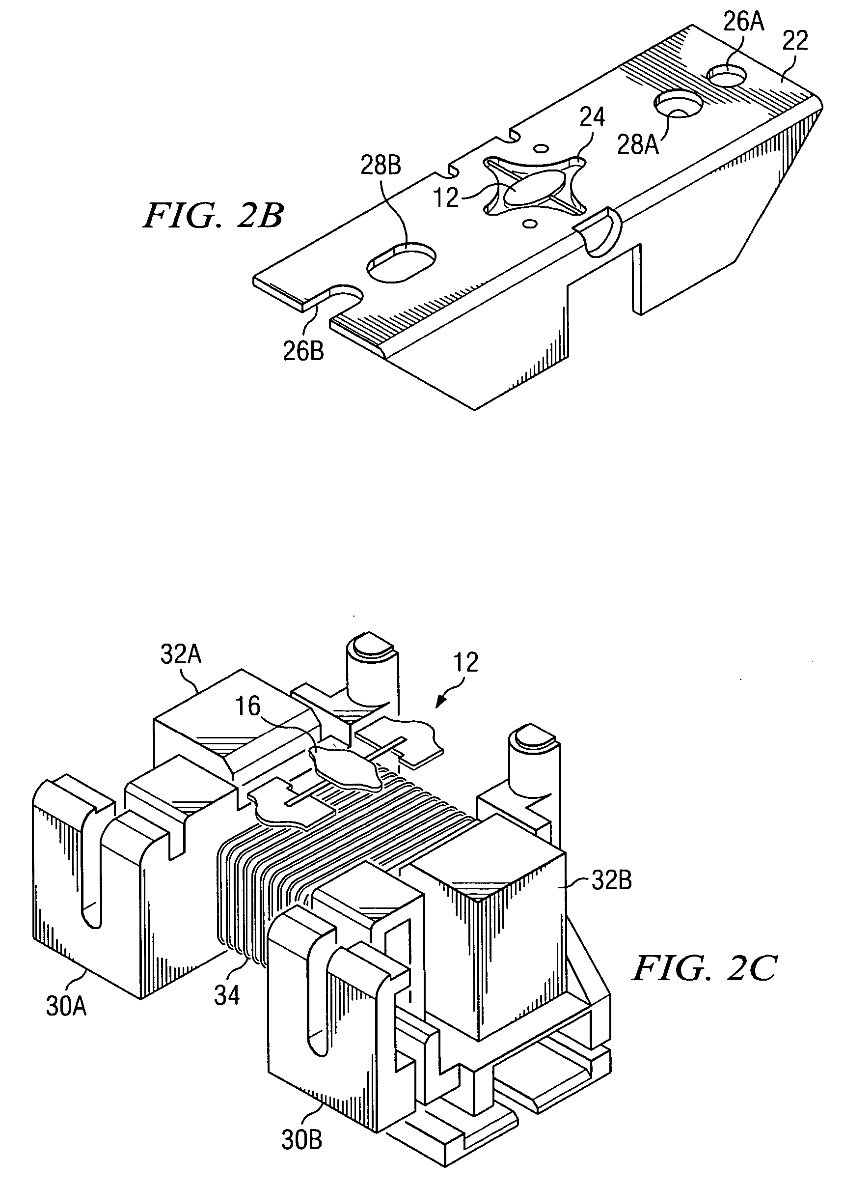
[0025] Referring now to FIG. 1, there is shown a presently available mirror package using torsional hinged mirrors. As shown, the combination package includes a support bracket 10, pivoting torsional hinged mirror device 12 and a drive mechanism (mostly obscured) 15.

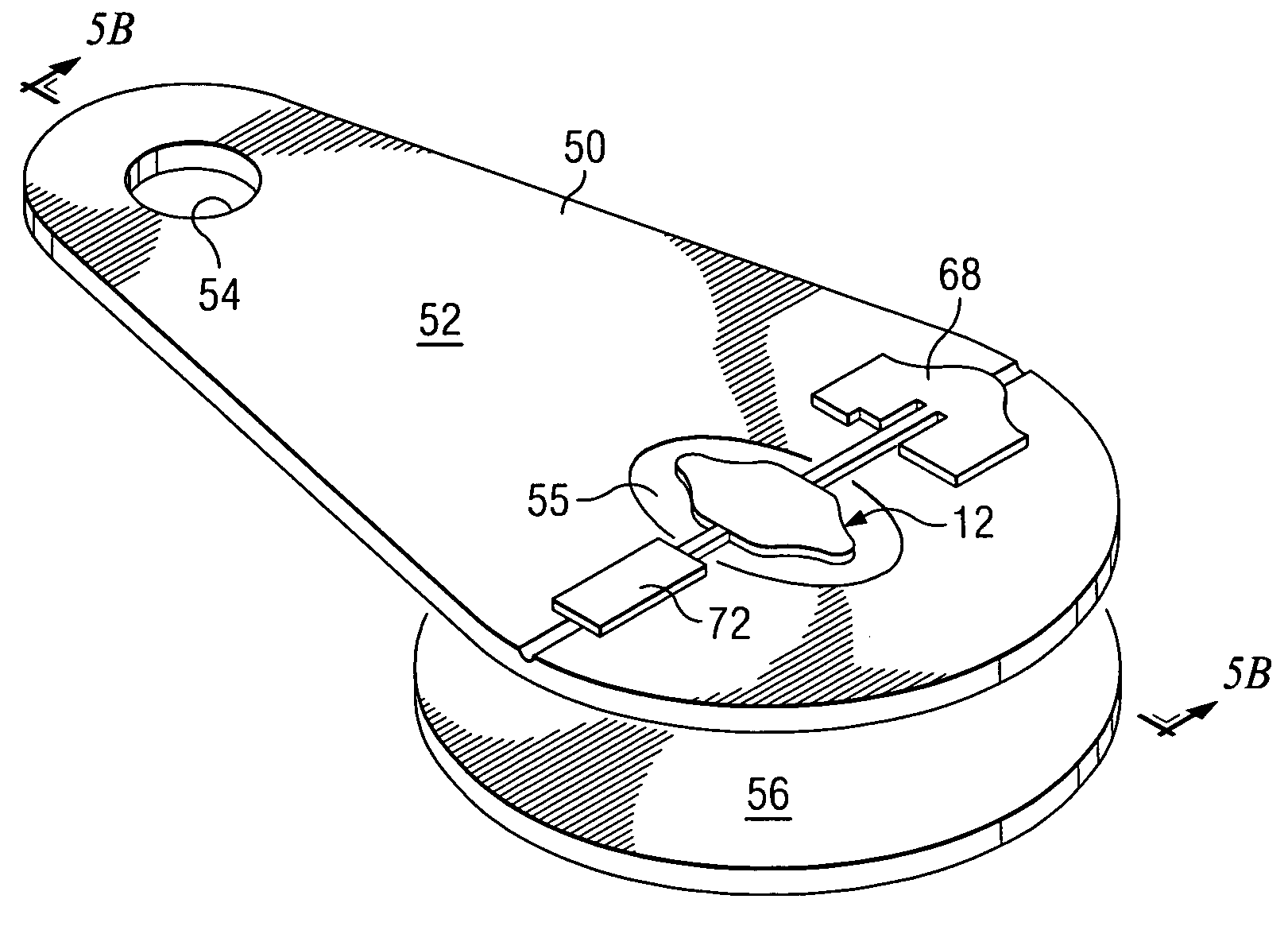
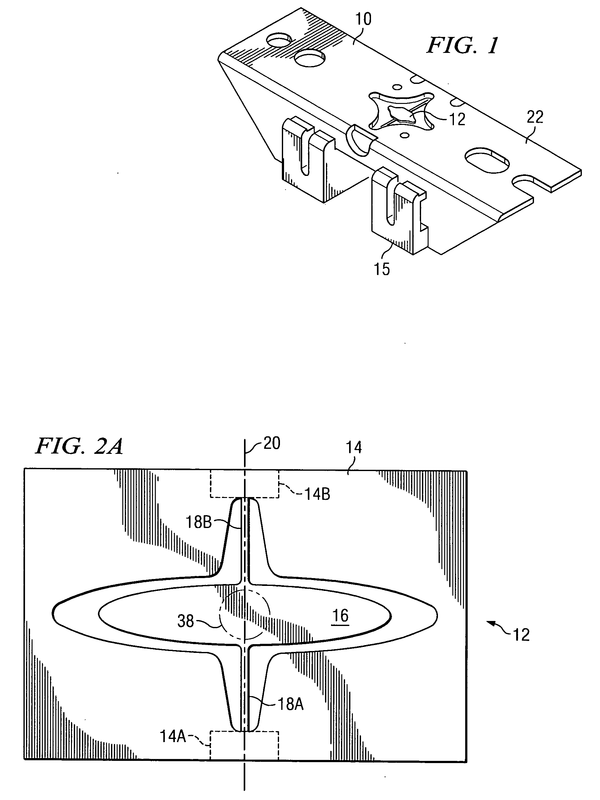
[0026] Various embodiments of torsional hinged mirrors may be used with the combination package illustrated in FIG. 1. However, FIG. 2A illustrates an example of a preferred long elliptical-shaped mirror for a using device such as a laser printer. As shown, the mirror device 12 will include an anchor such as fr...


PUM


Abstract

The present invention provide an inexpensive combination package of a pivoting mirror support structure and drive mechanism suitable for use for devices requiring a scanning light beam such as laser printers and other display devices. By using a single axis torsional mirror, and a unitary plastic support structure for supporting the mirror and the electrical windings, a very simple and inexpensive mirror package can be manufactured.

Description

TECHNICAL FIELD [0001] The present invention relates generally to the field of torsional hinge MEMS scanning engines and more particularly to methods and apparatus for providing an inexpensive combination of a pivoting mirror with a drive mechanism and support package. BACKGROUND [0002] The use of rotating polygon scanning mirrors in laser printers to provide a beam sweep or scan of the image of a modulated light source across a photo-resistive medium such as a rotating drum is well known. More recently, there have been efforts to use a much less expensive flat mirror with a single reflective surface such as a mirror oscillating in resonance to provide the scanning beam. These scanning mirrors provide excellent performance at a very advantageous cost. Unfortunately, the resonant frequency of the mirror as it pivots about its torsional hinges is highly susceptible to stresses that cause tension or compression of the hinges. Robust mounting brackets are typically used to mount the tor...

Claims


Application Information

Patent Timeline
Patent Type & Authority Applications(United States)
IPC IPC(8): G02B26/00
CPCG02B26/085
Inventor ORCUTT, JOHN W.
Owner TEXAS INSTR INC
Why Eureka
Try Eureka