
System for interfacing between an operator and a virtual object for computer aided design applications

a technology virtual objects, applied in the field of computer aided design systems, can solve the problems of limited nurbs paradigm, mainly used ffd, and not allowing for intuitive feel of sculpting procedures

Inactive Publication Date: 2006-06-08
KESAVADAS THENKURUSSI +2
View PDF3 Cites 34 Cited by
  • Summary
  • Abstract
  • Description
  • Claims
  • Application Information

AI Technical Summary

Benefits of technology

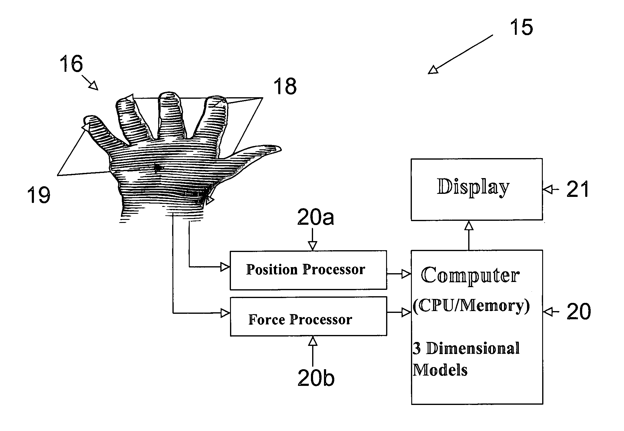
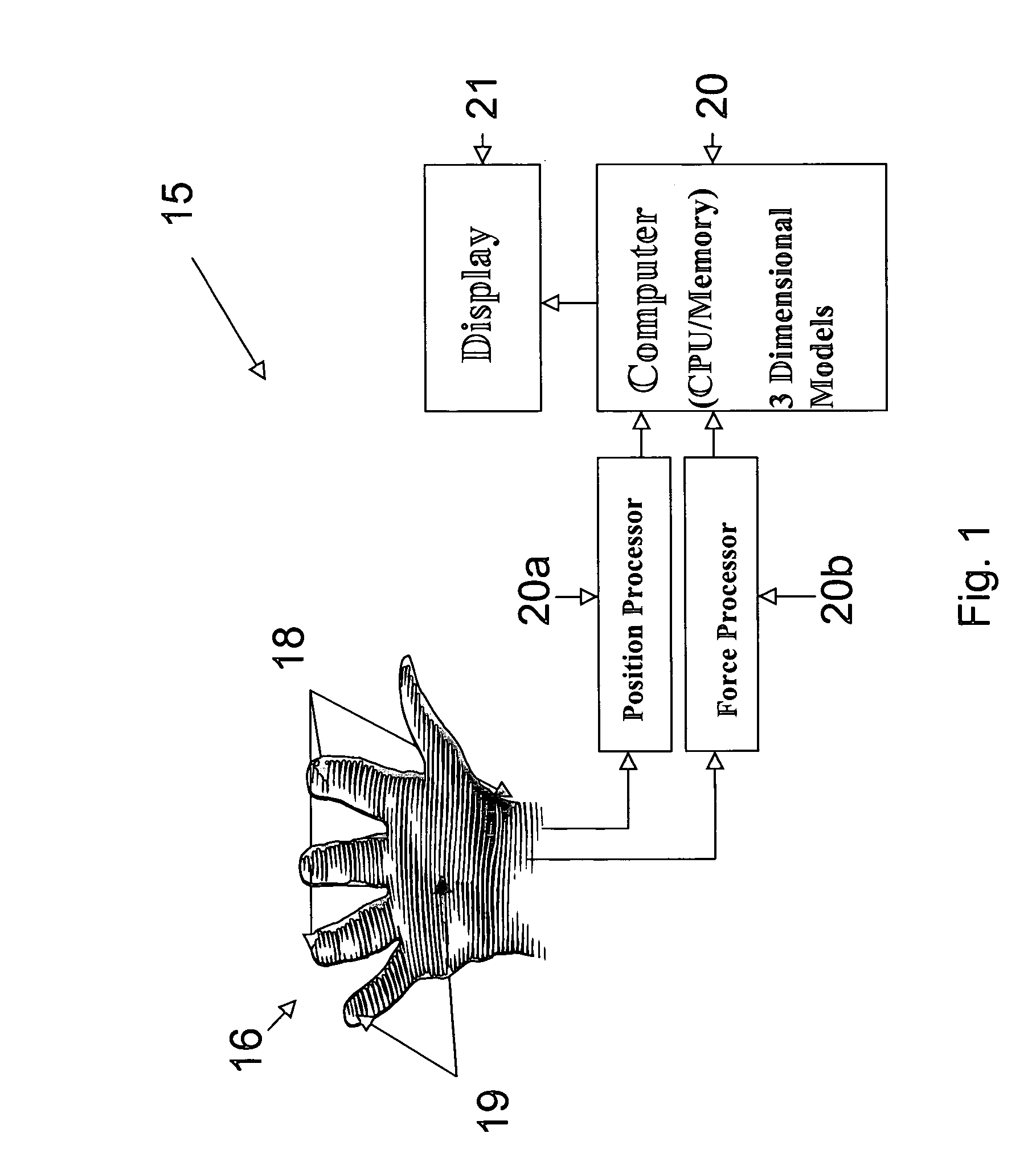
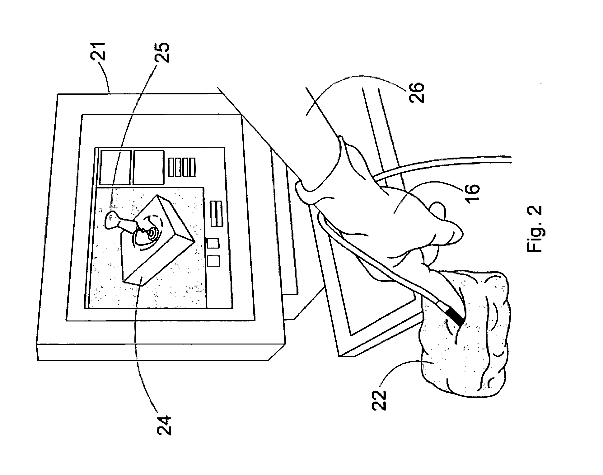
The invention is an improved apparatus for computer aided design applications that allows an operator to interface with a virtual object using a physical device. The device has sensors that detect force and position, and the sensors' signals are processed to select control points in force vectors. These vectors are then used to create a virtual representation of the object, which can be displayed on a screen. The virtual representation can also show the deformation of the object caused by the physical device. The apparatus can be used with different physical devices like a probe, finger, knife, stamp, pestle, hammer, or sculpting tool, and the control points can be manually entered or computed from dimensions. Overall, this invention provides a more intuitive and efficient way to work with virtual objects in computer aided design applications.

Problems solved by technology

The technical problem addressed in this patent text is the lack of effective tools for modifying and interacting with soft-based curved surfaces in a viscoelastic environment during the early stages of design. Current techniques require multiple steps and limit flexibility, including developing a roughness texture, dividing the surface into small sections, and utilizing separate devices for different types of interactions. Additionally, existing tools often struggle with handling larger surfaces and may not offer designers the desired level of detail needed for visual representation.

Method used


Image

  • System for interfacing between an operator and a virtual object for computer aided design applications
  • System for interfacing between an operator and a virtual object for computer aided design applications
  • System for interfacing between an operator and a virtual object for computer aided design applications

Examples


Embodiment Construction

[0037] At the outset, it should be clearly understood that like reference numerals are intended to identify the same structural elements, portions or surfaces, consistently throughout the several drawing figures, as such elements, portions or surfaces may be further described or explained by the entire written specification, of which this detailed description is an integral part. Unless otherwise indicated, the drawings are intended to be read (e.g., cross-hatching, arrangement of parts, proportion, degree, etc.) together with the specification, and are to be considered a portion of the entire written description of this invention. As used in the following description, the terms “horizontal”, “vertical”, “left”, “right”, “up” and “down”, as well as adjectival and adverbial derivatives thereof (e.g., “horizontally”, “rightwardly”, “upwardly”, etc.), simply refer to the orientation of the illustrated structure as the particular drawing figure faces the reader. Similarly, the terms “in...


PUM


Abstract

An apparatus (15) for interfacing between an operator (26) and computer generated virtual object comprising a force sensor (19) that provides a force signal as a function of the amount of force applied to a representative physical body (22), a position sensor (18) that provides a position signal representative of the location of the position sensor when the force is applied, an article (16) for coupling the force sensor and the position sensor to an extremity of an operator, and a processor system (20) communicating with the force sensor and the position sensor and adapted to deform a virtual object (24) as a function of the force signal and the position signal.

Description


Claims


Application Information

Patent Timeline
Owner KESAVADAS THENKURUSSI
Learn More