Engine knocking detection apparatus which adjusts passband of sensor signal bandpass filter in accordance with increases in crankshaft angle
- Summary
- Abstract
- Description
- Claims
- Application Information
AI Technical Summary
Benefits of technology
Problems solved by technology
Method used
Image

Examples
first embodiment
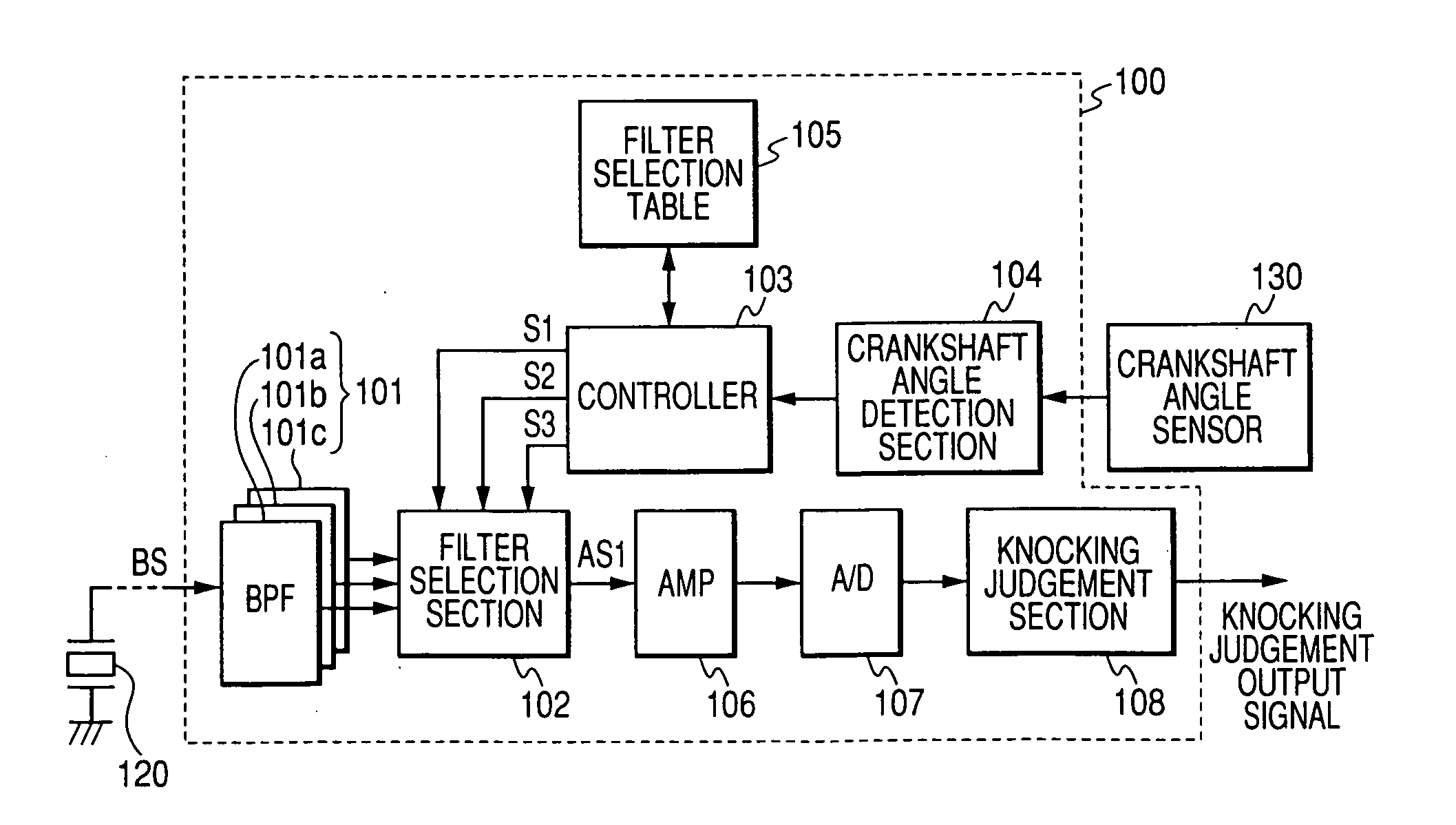
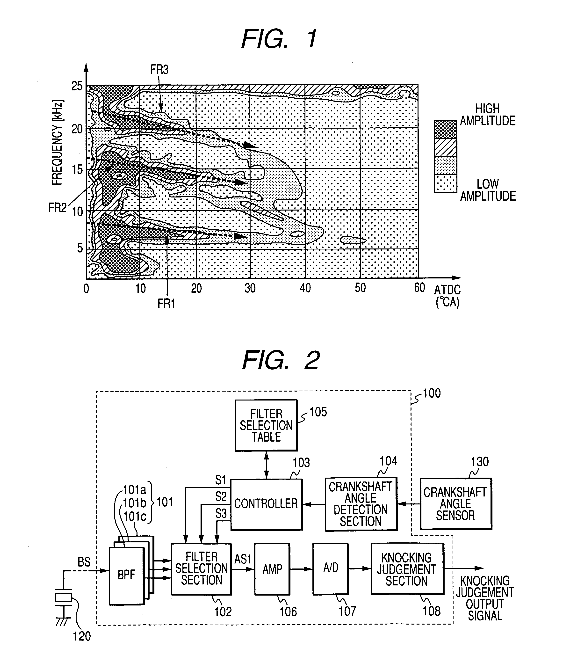
[0051]FIG. 2 is a general block diagram of a first embodiment of an engine knock detection apparatus. This embodiment is for use in a 4-cylinder 4-stroke internal combustion engine, so that there are four successive combustion stroke intervals in each 720° rotation angle of the engine crankshaft, as measured starting from the TDC (top dead center) position in a specific cylinder. That is, each combustion stroke interval corresponds to 180° rotation of the crankshaft, as measured from a TDC point. In the following, “amount of crankshaft rotation angle after TDC” will be abbreviated as “CA ATDC”.
[0052] Thus, with one of the engine cylinders designated as the No. 1 cylinder, and the remaining three cylinders whose ignition times respectively succeed that of the No. 1 cylinder being designated as the No. 2 cylinder, the No. 3 cylinder and the No. 4 cylinder, the respective combustion stroke intervals of these cylinders in each 720° rotation of the crankshaft correspond to the following...
second embodiment
[0088] A second embodiment will be described in the following, which also is an engine knocking detection apparatus applicable to a 4-cylinder internal combustion engine, as for the first embodiment. Whereas the first embodiment performs bandpass filtering by selecting one of a plurality of bandpass filters having respectively different center frequencies, with the second embodiment a (single) variable center frequency type of bandpass filter is utilized, whose passband characteristic is adjusted by altering the center frequency of the passband, by a control signal.
[0089]FIG. 6 is a general block diagram of the engine knocking detection apparatus 200 of this embodiment, which differs from that of FIG. 1 in that a variable center frequency bandpass filter 201 replaces the bandpass filter set 101, and in that a controller 203 generates an appropriate control signal for controlling the passband characteristic of the variable bandpass filter 201, while in addition a filter characterist...
third embodiment
[0102] A third embodiment will be described in the following, which is an engine knocking detection apparatus that is applicable to a 4-cylinder internal combustion engine, as for the preceding embodiments. With the third embodiment, three bandpass filters are utilized which respectively correspond to the knocking frequencies FR1, FR2, FR3 shown in FIG. 1 and described above. The respective center frequencies of these bandpass filters are shifted successively downward, during the first part of each combustion stroke interval, in accordance with changes in these knocking frequencies, as the crankshaft angle advances.
[0103]FIG. 10 is a general block diagram of the engine knocking detection apparatus 300 of the third embodiment, in which the sensor signal BS from the knocking sensor 120 is first transferred through a low-pass filter 301. The low-pass filter 301 serves as an anti-aliasing filter, removing certain high-frequency components of the sensor signal BS, for the purposes of su...
PUM
 Abstract
Description
Claims
Application Information
 - R&D
- Intellectual Property
- Life Sciences
- Materials
- Tech Scout
- Unparalleled Data Quality
- Higher Quality Content
- 60% Fewer Hallucinations
Browse by: Latest US Patents, China's latest patents, Technical Efficacy Thesaurus, Application Domain, Technology Topic, Popular Technical Reports.
© 2025 PatSnap. All rights reserved.Legal|Privacy policy|Modern Slavery Act Transparency Statement|Sitemap|About US| Contact US: help@patsnap.com