Eureka AIR delivers breakthrough ideas for toughest innovation challenges, trusted by R&D personnel around the world.

Core structure of a gun trigger lock

a gun trigger lock and core structure technology, applied in the direction of weapons, weapon components, safety arrangements, etc., can solve the problems of high manufacturing cost and obvious trouble in managing so many locks and keys, and achieve the effect of convenient and convenient use and management without disabling the overall function of the gun trigger lock

Inactive Publication Date: 2006-06-08
CHANG WEN KWEI
View PDF8 Cites 25 Cited by
  • Summary
  • Abstract
  • Description
  • Claims
  • Application Information

AI Technical Summary

Benefits of technology

[0010] The primary purpose of the present invention is to improve and create a new core structure of a gun trigger lock. The primary object of the invention is to make it easy and convenient to use and manage the gun trigger lock by modifying the key design with corresponding bump in the straight core rod, and without disabling overall functions of the gun trigger lock.
[0011] Another object of the invention is to reduce the manufacturing cost and selling price of the gun trigger lock by the simpler core structure than previous arts.

Problems solved by technology

However, the prior arts involve complicated structures and many components to fabricate the gun trigger lock and much time to assemble it, which results in high manufacturing cost.
It is obvious a trouble to manage so many locks and keys.

Method used


Image

  • Core structure of a gun trigger lock
  • Core structure of a gun trigger lock
  • Core structure of a gun trigger lock

Examples


Embodiment Construction

[0031] The following descriptions are of exemplary embodiments only, and are not intended to limit the scope, applicability or configuration of the invention in any way. Rather, the following description provides a convenient illustration for implementing exemplary embodiments of the invention. Various changes to the described embodiments may be made in the function and arrangement of the elements described without departing from the scope of the invention as set forth in the appended claims.

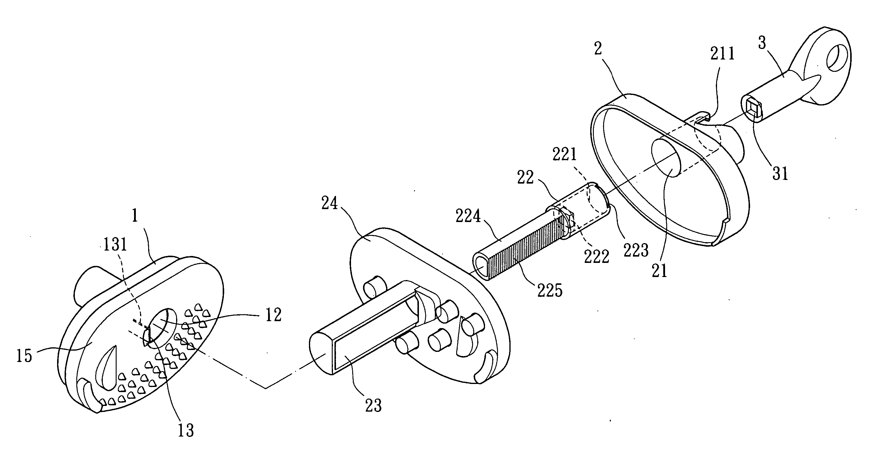
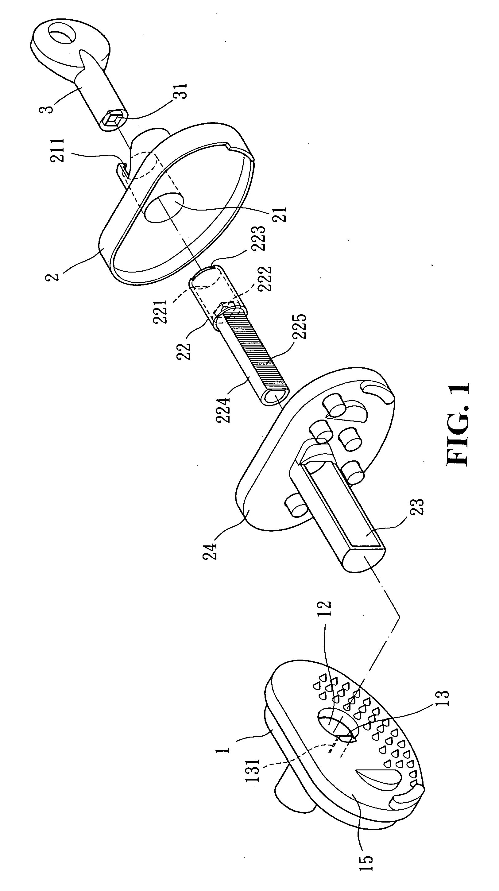
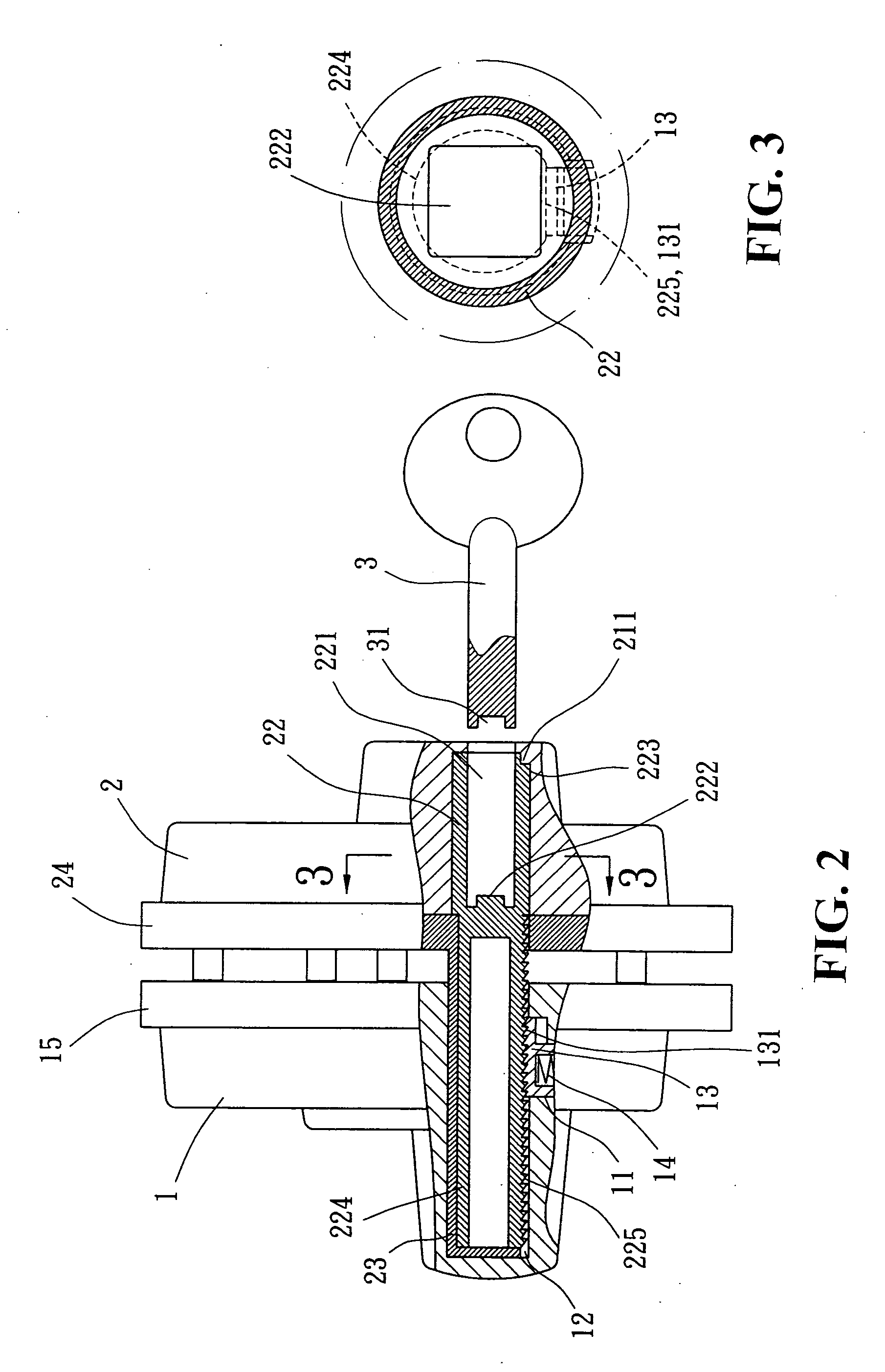
[0032] As shown in FIGS. 2 and 3, the gear shaft 224 and the open groove 23 of the second embedded part 2 can be matched well and inserted into the straight hole 12 of the first embedded part 1. By intermeshing the ratchets 225 on one side of the gear shaft 224 in the second embedded parts 2 and the ratchets 131 on one side of the lock piece 13, the two embedded parts 1, 2 of the present invention are locked, as shown in FIG. 2.

[0033] The two embedded parts 1, 2 of the present invention can be...


PUM


Abstract

A core structure of gun trigger lock comprises two embedded parts. A first embedded part includes a pit and a straight hole; a lock piece and a spring are disposed in the pit; the lock piece, having parallel ratchets formed on one side, is pushed by the spring and moves upward constantly. A second embedded part includes a core rod hole, and a straight core rod is disposed therein; the straight core rod includes a long keyhole at the open end, and a aspheric bump is placed at the bottom of the keyhole; a gear shaft, having parallel ratchets on one side, extends from the straight core rod and can be inserted into the straight hole of the first embedded part. Moreover, a key is also included in the present invention, having an aspheric pit at the front end which matches with the shape of the aspheric bump at the bottom of the keyhole of the second embedded part. Thus, by turning the key to rotate the straight core rod together with the gear shaft, the first and second embedded parts can be combined together or released separately.

Description

BACKGROUND OF THE INVENTION [0001] (a) Technical Field of the Invention [0002] The present invention relates to a core structure of a gun trigger lock, and more particularly, to a gun trigger lock comprising two embedded parts. The main structure comprises a straight core rod inserted in the core rod hole of one of the embedded parts. A long keyhole is formed at the open end of the straight core rod, having an aspheric bump at the bottom of the keyhole. Moreover, a key shapes a pit corresponding to the bump at its front end. The key can insert into the long keyhole of the straight core rod to turn the rod rotating, and then to lock the two embedded parts by meshing the ratchet wheels, or to release the two embedded parts by separating the ratchet wheels. [0003] The present invention comprises a first embedded part and a second embedded part which can be combined together or release separately. The two embedded parts can lock the gun trigger and trigger guard to disable the gun, prev...

Claims


Application Information

Patent Timeline
Patent Type & Authority Applications(United States)
IPC IPC(8): F41A17/00
CPCF41A17/02F41A17/54
Inventor CHANG, WEN-KWEI
Owner CHANG WEN KWEI
Why Eureka
Eureka Blog
Learn More