
Door hanging assembly

Inactive Publication Date: 2006-02-09
LAMPE JOHN K +1
View PDF23 Cites 11 Cited by
  • Summary
  • Abstract
  • Description
  • Claims
  • Application Information

AI Technical Summary

Benefits of technology

[0010] This invention encompasses embodiments with one or more of the following objects. The advantages and objects of this invention include:
[0011] A door banner that is safe for use; that is easy and convenient to use; that can be packaged for easy storage, shipping, and opening by the user; that is easy and economical to manufacture; that does not damage structures from which it is hung or other structures or items near the banner.
[0012] A door banner whose functions could include: displaying various images such as decorative ones (e.g., holiday themes) or

Problems solved by technology

However, attaching decorations to a garage door presents challenges.
Otherwise the decoration or, worse, the garage door or garage door frame may be damaged.
Moreover, the exterior surface of garage doors are exposed to the elements.
Wind, moisture, cold, heat, and sunshine can all damage decorations and make secure attachment more difficult.
The prior art suffers from certain shortcomings or limitations.

Method used


Image

  • Door hanging assembly
  • Door hanging assembly
  • Door hanging assembly

Examples


first embodiment

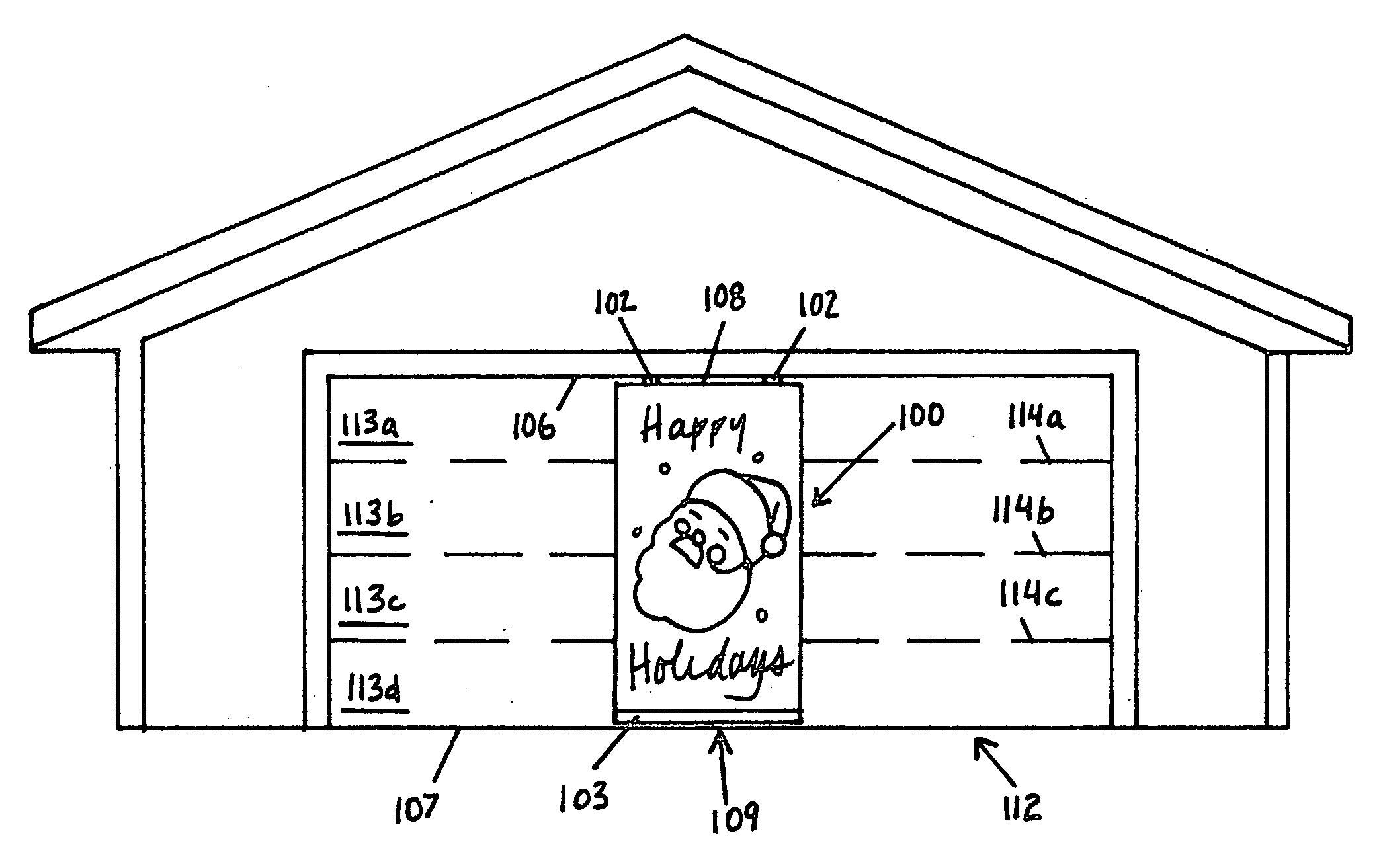
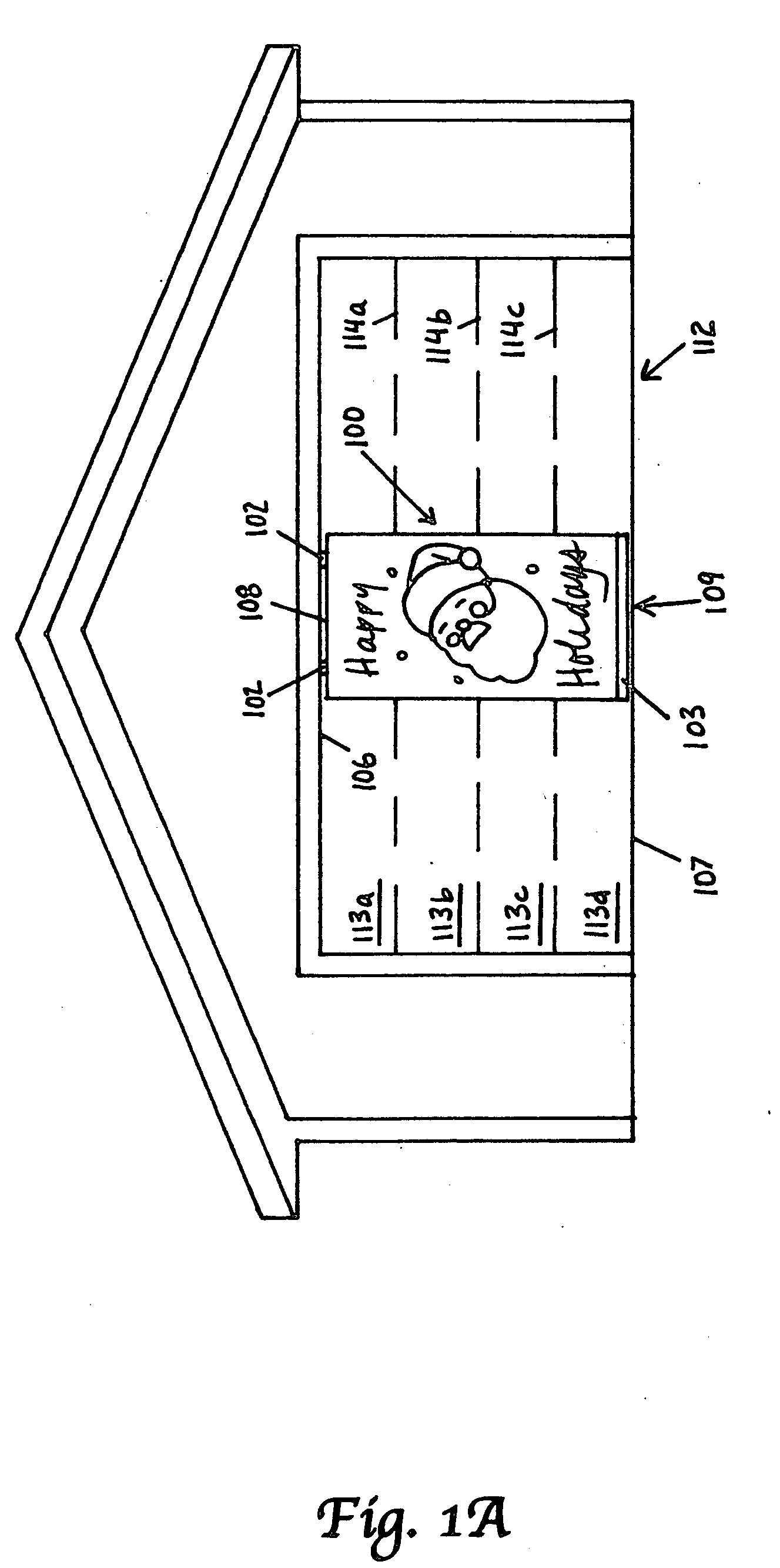
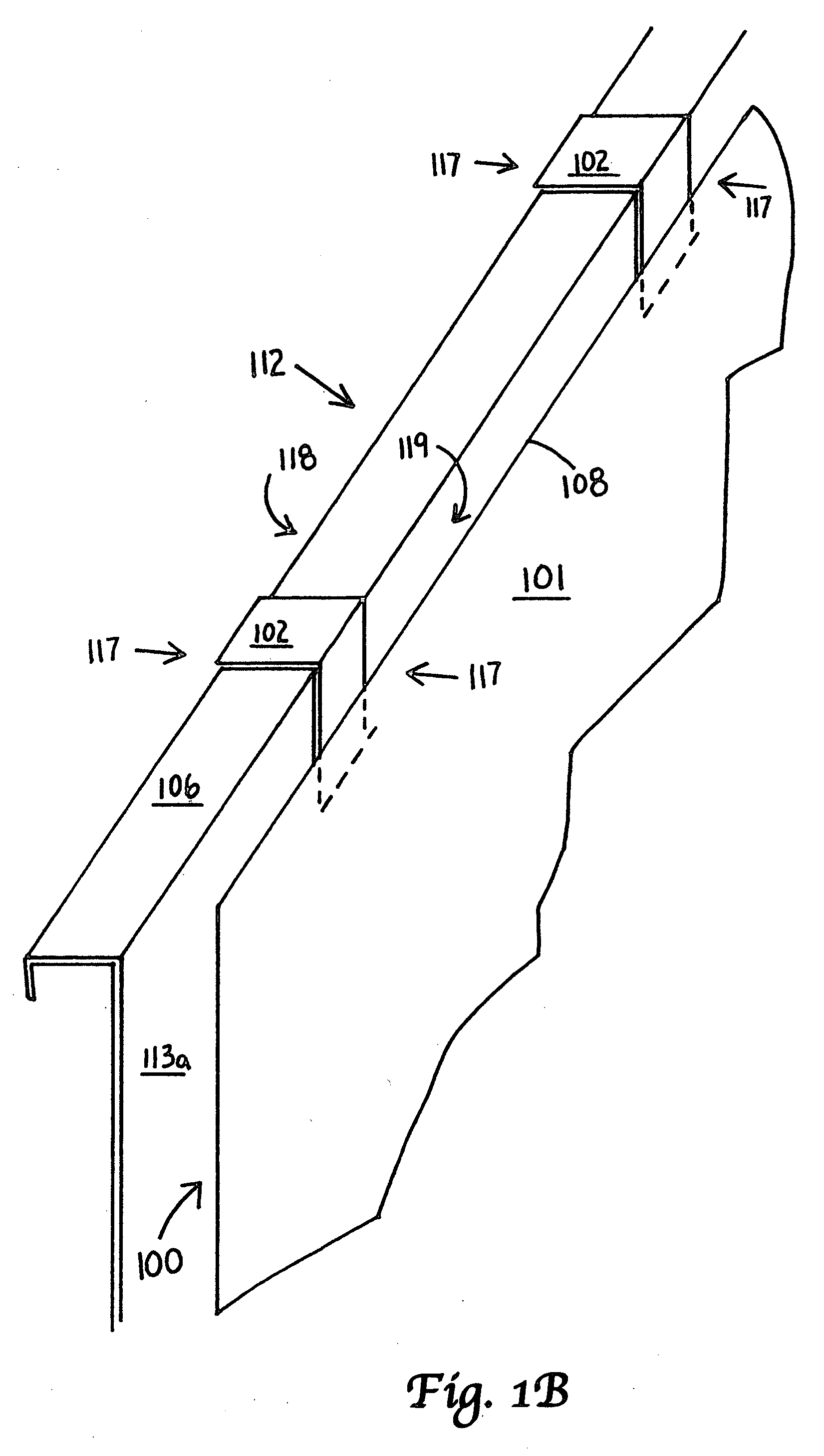
[0225]FIGS. 1A to 1G show a garage door banner 100 according to a first embodiment of the invention. The garage door banner 100 could consist of a flexible sheet 101, attachment means 102, and a stabilizer 103.

[0226] The flexible sheet 101 shown in FIGS. 1A to 1D could be made of a lightweight fabric. The images 104 could be printed on the flexible sheet 101. As shown in FIG. 1G, the flexible sheet 101 could have a grid of holes 105 through the sheet 101. Such a grid 105 could reduce billowing of the flexible sheet 101 in the wind. Such a grid 105 could easily be created using a mesh fabric or a nonwoven fabric with perforations. In addition, if the flexible sheet 101 were made of plastic, the grid 105 could be created relatively easily with a punching or other fabrication process.

[0227] The attachment means 102 could have a C-shape and could fit over the top edge 106 of the garage door 112. FIG. 1B shows two C-shaped attachment means 102. The attachment means 102 could be permane...

second embodiment

[0233]FIGS. 2A and 2B show a door banner 200 according to the second embodiment. The banner 200 could substantially resemble the banner 100 shown in relation to FIGS. 1A to 1G with one primary difference. The attachment means 202 for banner 200 could be integrated into an upper stabilizer. The upper stabilizer 225 could help maintain the shape of the banner 200 and could complement a lower stabilizer (not shown) on the bottom edge (not shown) of the banner 200.

third embodiment

[0234]FIGS. 3A and 3B show a garage door banner 300 according to the third embodiment. The banner 300 could substantially resemble the banner 100 shown in relation to FIGS. 1A to 1G with the primary difference being the attachment means 302 for banner 300. The attachment means for banner 300 could consist of a contact pad 330 that attaches to the interior side 318 of the top section of the garage door. The contact pad 330 could use magnets or adhesive to attach to the interior surface 318 of the door. A magnetic contact pad 330 could work on a metallic garage door 312. The flexible sheet 301 could simply drape over the top edge 306 of the garage door 312 as shown in FIG. 3A.


PUM


Abstract

A door hanging assembly for hanging on a sectional garage door. The door hanging assembly includes a hung object with a top end and a bottom end and at least one hook configured and arranged for hanging the top end of the hung object on the top edge of the top section of the garage door. The door hanging assembly can further include at least one stabilizer affixed to the bottom end of the hung object to maintain the bottom end of the hung object between the top edge and the bottom edge of one section when the garage door opens and closes.

Description

[0001] This application claims the benefit of U.S. Provisional Applications No. 60 / 591,178 filed on Jul. 26, 2004, and No. 60 / 637,416 filed on Dec. 20, 2004.FIELD OF INVENTION [0002] The present invention generally relates to a decorative or novelty device. Specifically, the device is a door hanging for hanging on doors such as garage doors or doors of homes. The door hanging could display decorative or utilitarian images including graphic, cut-out, or three-dimensionally shaped images. BACKGROUND OF INVENTION [0003] Doors present an ideal location for displays of various kinds including decorative ones. This is especially true of garage doors on residential homes. For many homes the garage door offers a large, prominent, substantially flat surface for display. [0004] However, attaching decorations to a garage door presents challenges. Garage doors, when being opened and closed, have moving parts. More specifically, each section of a sectional garage door typically installed at most...

Claims


Application Information

Patent Timeline
IPC IPC(8): E05D15/00
CPCE06B3/7001G09F19/22E06B2003/7044
Inventor LAMPE, JOHN K.OUDEKERK, DOUGLAS R.
Owner LAMPE JOHN K
Learn More