Data driving circuit, organic light emitting display including the same, and driving method thereof

a driving circuit and data technology, applied in the direction of instruments, static indicating devices, electroluminescent light sources, etc., can solve the problems of increasing production costs, limiting the design increasing the size of the data driving circuit, so as to reduce the production cost, and reduce the number of wiring lines

Inactive Publication Date: 2006-06-01
SAMSUNG DISPLAY CO LTD
View PDF8 Cites 9 Cited by
  • Summary
  • Abstract
  • Description
  • Claims
  • Application Information

AI Technical Summary

Benefits of technology

[0013] Accordingly, it is an aspect of the present invention to provide a data driving circuit, an organic light emitting display including the data driving circuit and a driving method for the display, where the data driving circuit has an improved wiring structure to secure design freedom and decrease the total size of the organic light emitting display.
[0020] An embodiment of the present invention provides a data driving circuit for an organic light emitting display and a method for driving the display where a pair of sampling latches and a pair of holding latches of the data driving circuit share wiring lines with each other to transmit data. As the pairs of sampling and holding latches share the wiring lines required for transmitting the data, the number of wiring lines is reduced approximately in half as compared with the conventional schemes, allowing design freedom for the data driving circuit and decreasing its production cost. Further, as the number of wiring lines is reduced, the size of the data driving circuit is decreased as compared with the conventional data driving circuit.

Problems solved by technology

This causes the size of the data driving circuit to increase.
Using a large number of wiring lines between the sampling latch part 10 and the holding latch part 20 not only limits the design of the data driving circuit but also increases production cost.

Method used


Image

  • Data driving circuit, organic light emitting display including the same, and driving method thereof
  • Data driving circuit, organic light emitting display including the same, and driving method thereof
  • Data driving circuit, organic light emitting display including the same, and driving method thereof

Examples


Embodiment Construction

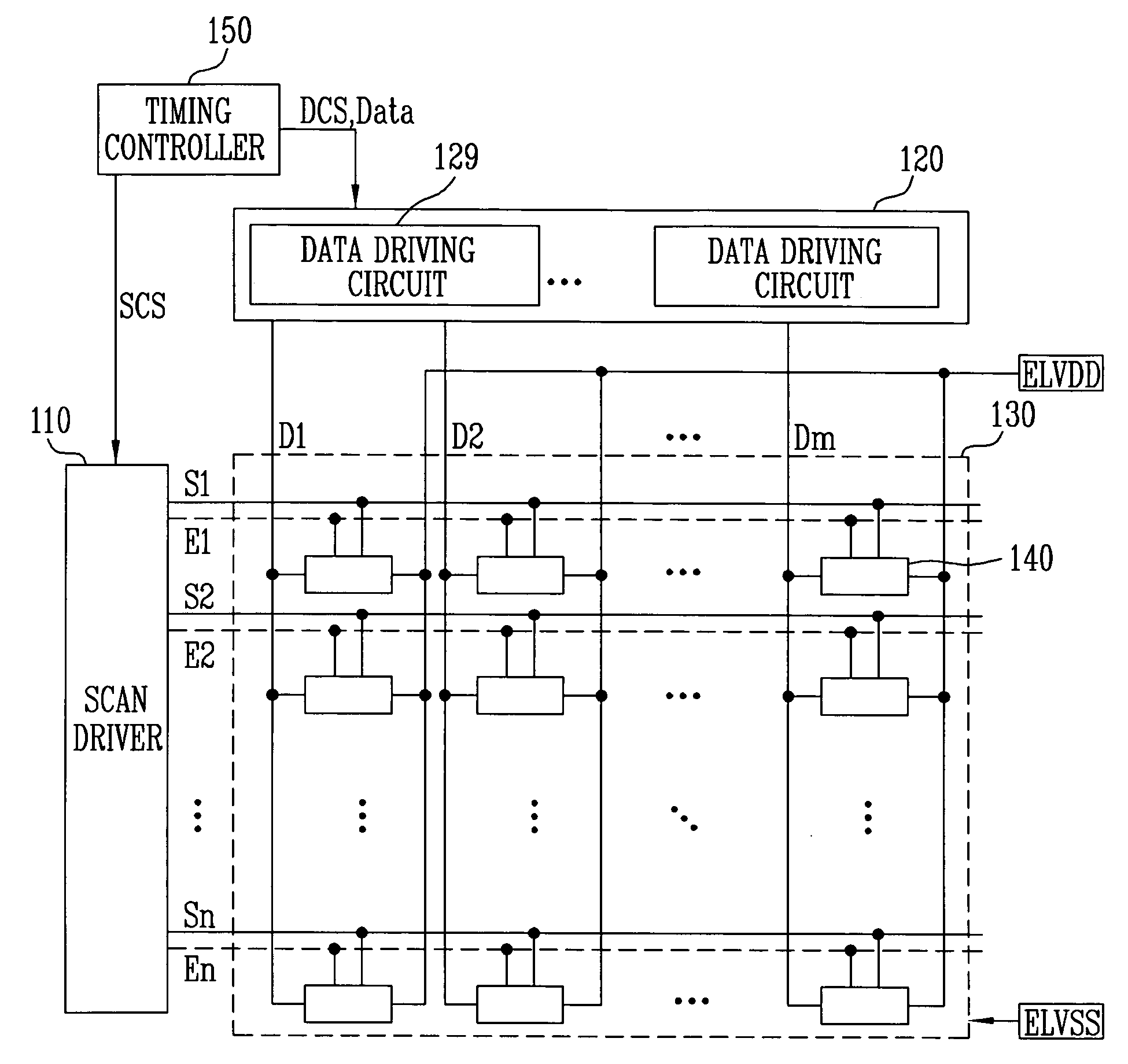
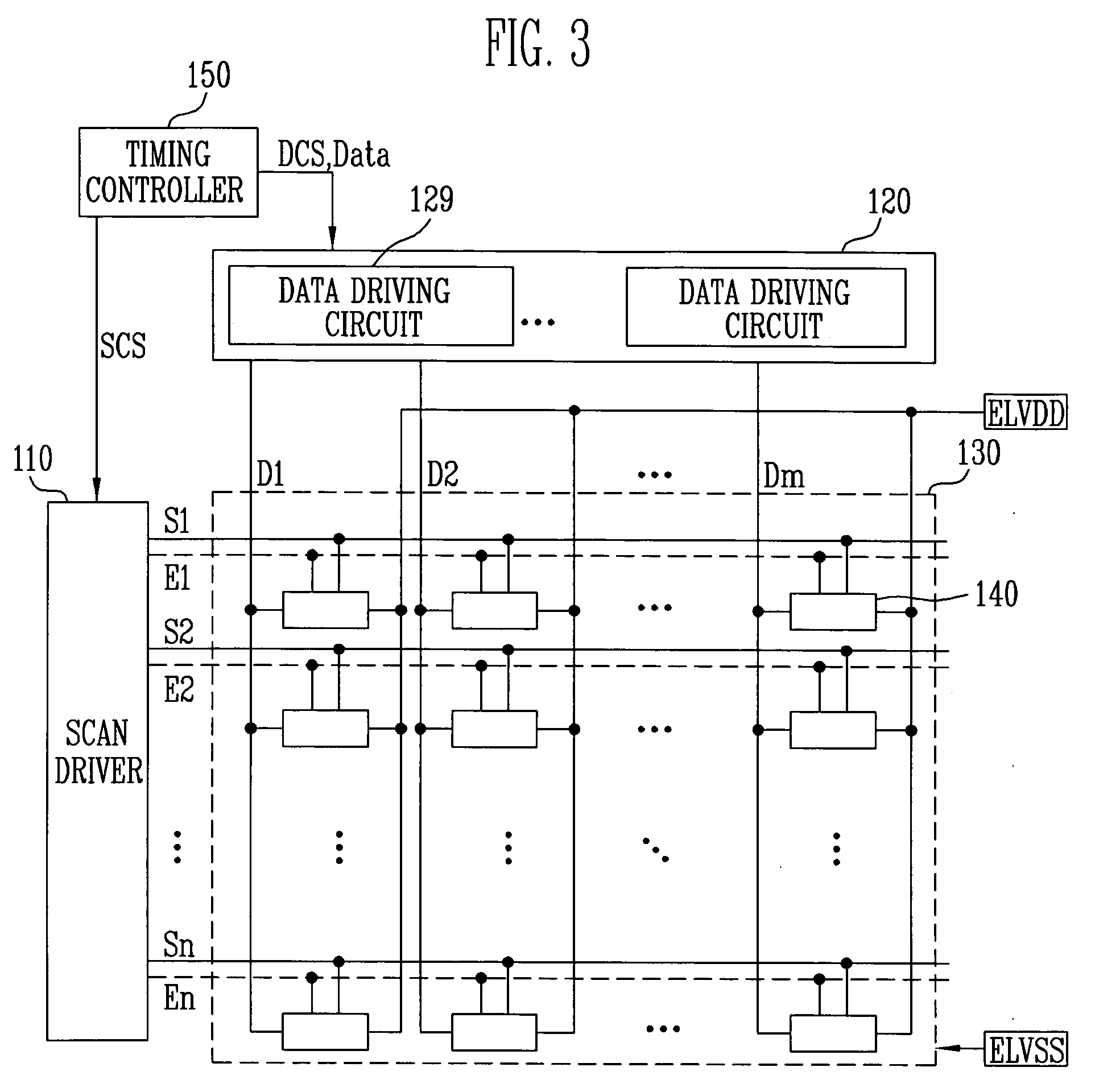
[0029]FIG. 3 illustrates an organic light emitting display according to an embodiment of the present invention. An organic light emitting display according to an embodiment of the present invention includes a pixel portion 130 including a plurality of pixels 140 formed in regions where scan lines S1 through Sn intersect data lines D1 through Dm. The display also includes a scan driver 110 to drive the scan lines S1 through Sn, a data driver 120 to drive the data lines D1 through Dm, and a timing controller 150 to control the scan driver 110 and the data driver 120.

[0030] The scan driver 110 generates scan signals in response to a scan control signal SCS received from the timing controller 150, and supplies the scan signals to the scan lines S1 through Sn. The scan driver 110 also generates emission control signals in response to the scan control signal SCS, and supplies the emission control signals to emission control lines E1 through En.

[0031] The data driver 120 generates data s...


PUM


Abstract

A data driving circuit for an organic light emitting display and a method of driving the display where the number of wiring lines is reduced approximately in half as compared with the conventional schemes. The data driving circuit includes a shift register generating sampling signals in sequence, a sampling latch part sequentially storing data when the sampling signal is supplied, outputting some of the data in response to a first control signal, and outputting the rest of the data in response to a second control signal, a holding latch part receiving said some of the data in response to the first control signal, and receiving said rest of the data in response to the second control signal, and a digital-to-analog converter converting the data stored in the holding latch part into an analog data signal corresponding to a gradation level.

Description

CROSS-REFERENCE TO RELATED APPLICATION [0001] This application claims priority to and the benefit of Korean Patent Application No. 2004-90401, filed on Nov. 8, 2004, in the Korean Intellectual Property Office, the entire content of which is incorporated herein by reference. FIELD OF THE INVENTION [0002] The present invention relates to a data driving circuit, an organic light emitting display including the data driving circuit and a driving method for the display, where the data driving circuit has an improved wiring structure to secure design freedom and decrease the total size of the organic light emitting display. BACKGROUND OF THE INVENTION [0003] Various flat panel displays have recently been developed as alternatives to a relatively heavy and bulky cathode ray tube (CRT) display. The flat panel displays include liquid crystal displays (LCD), field emission displays (FED), plasma display panels (PDP), organic light emitting displays, and the like. [0004] Among the flat panel di...

Claims


Application Information

Patent Timeline
Patent Type & Authority Applications(United States)
IPC IPC(8): G09G3/30H05B44/00
CPCG09G3/3275G09G2310/027G09G2310/0297G09G3/30
Inventor CHOI, SANG MOO
Owner SAMSUNG DISPLAY CO LTD
Why Eureka
Try Eureka