
Smart antenna, method and apparatus for adaptive beam forming

a smart antenna and beam forming technology, applied in the field of radio communication, can solve the problems of multipath time delay, inability to search out time delay information accurately, and inability to solve multipath time delay

Inactive Publication Date: 2006-06-01
ZTE CORP
View PDF3 Cites 7 Cited by
  • Summary
  • Abstract
  • Description
  • Claims
  • Application Information

AI Technical Summary

Problems solved by technology

At present, there are many beam forming algorithms for smart antennas, but the common disadvantage of them consists in that it does not solve the problem of multipath time delay.
In the Chinese patent application with a publication number of 1235391, named “Adaptive Array Antenna Optimizing and Forming Beams in Advance for Code Division Multiple Access System”, the calculation of the weight in complex number is divided into two parts, i.e. initial weight designing and operational weight processing, since this application does not solve the problem of time delay accuracy and it requires a high initial weight, the performance of the smart antenna is hardly ensured.
Because it is crucial for an adaptive beam forming method to determine the multipath time delay accurately, how to search out the time delay information accurately is a problem which should be solved by the prior arts urgently.

Method used


Image

  • Smart antenna, method and apparatus for adaptive beam forming
  • Smart antenna, method and apparatus for adaptive beam forming
  • Smart antenna, method and apparatus for adaptive beam forming

Examples


Embodiment Construction

[0014] An embodiment of the present invention will now be described with reference to the drawings.

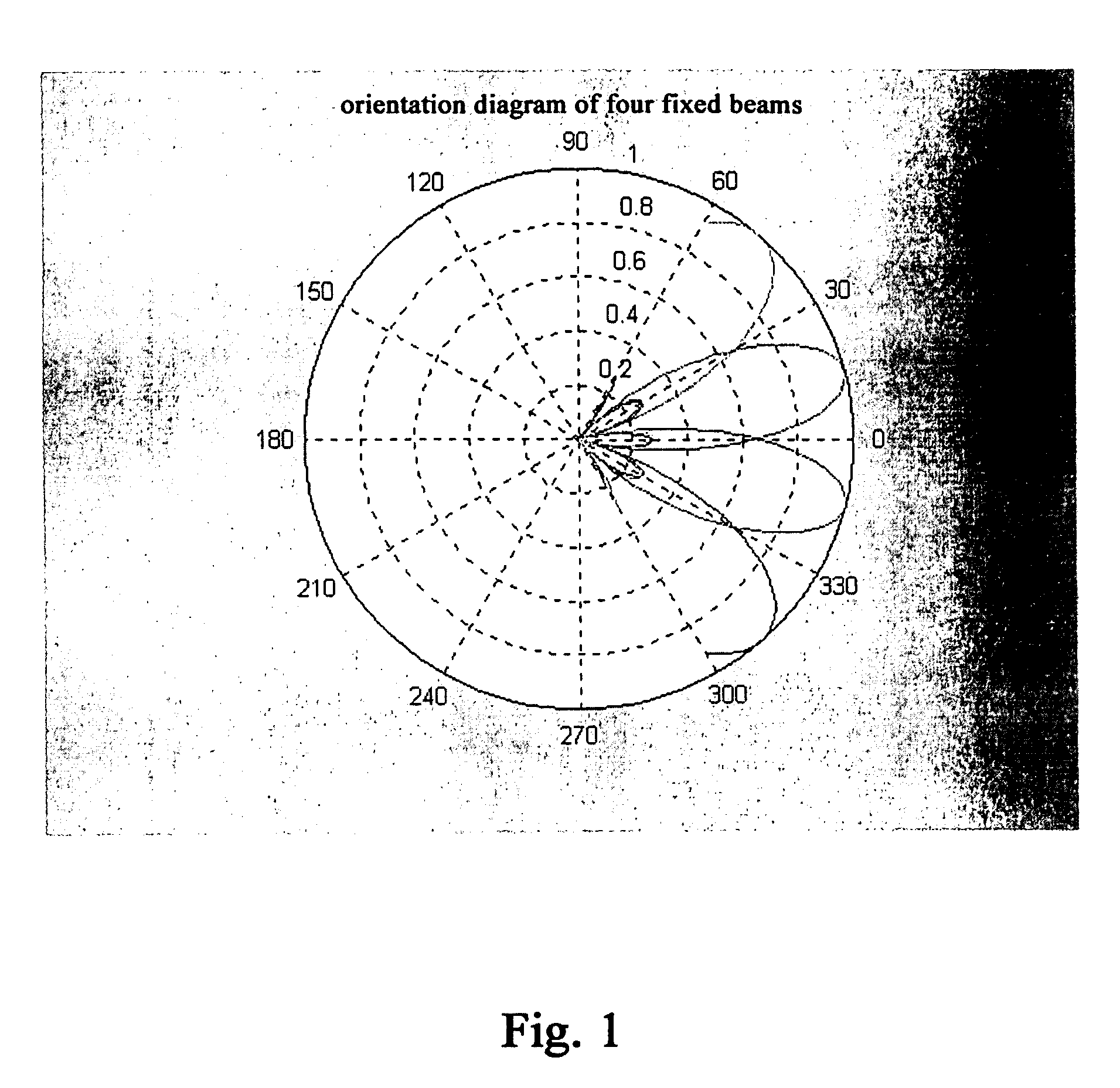
[0015]FIG. 1 is a beam orientation diagram, in which shown that four beams can magnificently cover a sector of 120° in a range of −60°˜60°, and the side lobes are low.

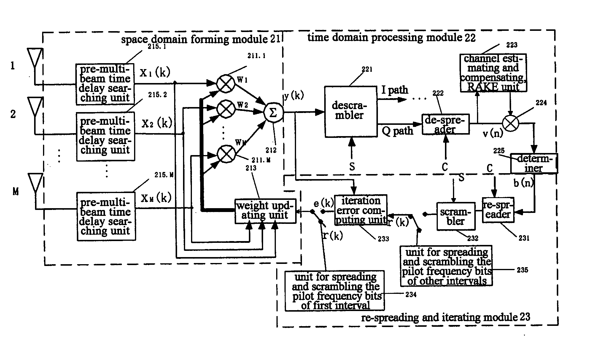
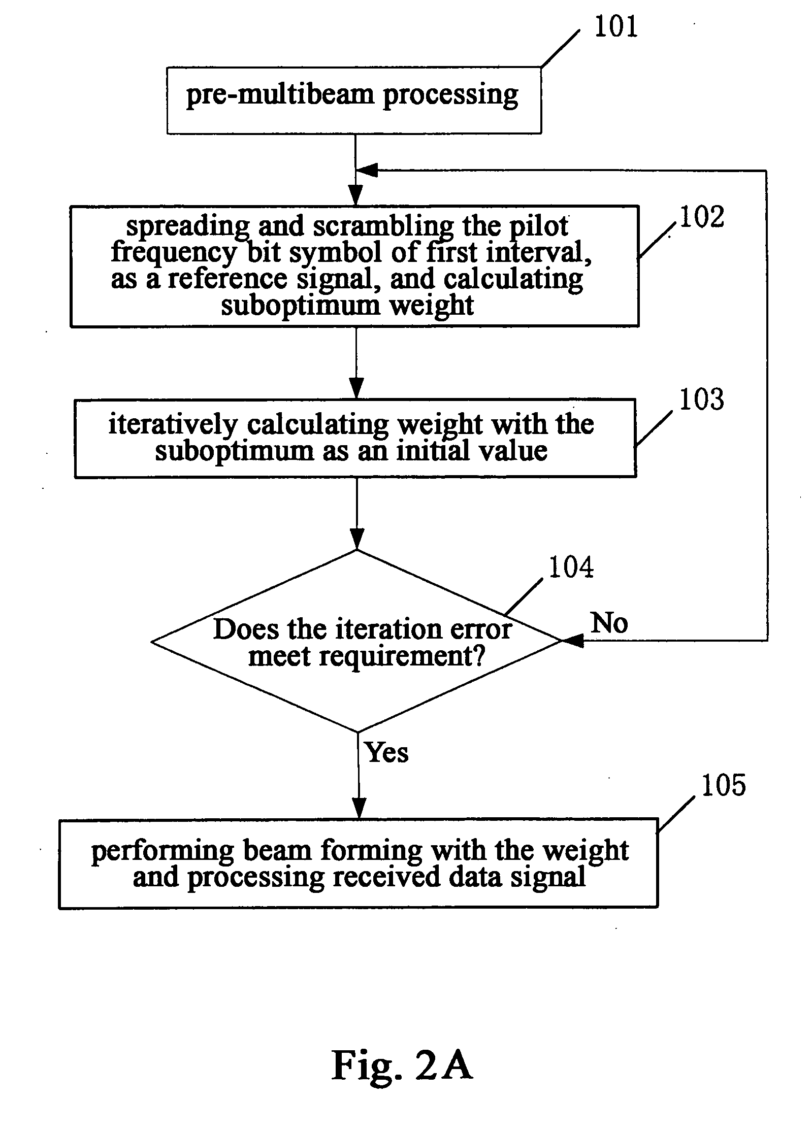
[0016]FIG. 2A is a flow chart showing the beam forming method according to a preferred embodiment of the present invention. As shown in FIG. 2A, in Step 101 firstly, in order to obtain the accurate time delays of respective multipathes before the adaptive beam forming, so as to ensure the beam forming of the smart antenna to be more reliable, the received arrays are implemented pre-multibeam processing in parallel simultaneously during the process of calculating the adaptive weight to supply an array received signal with aligned time delays to the adaptive weight calculation in real time.

[0017] More particularly, the processing includes generating a number of fixed narrow beams covering the sector, for example, in an e...


PUM


Abstract

The present invention discloses a beam forming method for a smart antenna and a beam forming apparatus for a smart antenna. Said method comprises: implementing pre-multibeam processing and time delay aligning to array signals; calculating a suboptimum weight by means of a pilot frequency symbol; iteratively calculating an optimum weight with said suboptimum weight as an initial value; forming beams by means of said optimum weight. To use the beam forming method and apparatus of the present invention, it can reduce the bit error ratio for receiving and outputting greatly and avoid the multiplication between large matrixes and matrix inversion and then replace them by simple addition and multiplication, so as to reduce the difficulty for hardware implement and make it easier to be performed.

Description

FIELD OF THE INVENTION [0001] The present invention relates to radio communication field, more particularly, to a technique for the adaptive beam forming of a smart antenna. BACKGROUND OF THE INVENTION [0002] With the rapid development of modern digital signal processing technology in recent years, continuously the processing capability of a DSP chip is enhanced and the price of the chip is reduced, so that it is possible to form antenna beams at baseband with digital technology, therefore the smart antenna technology with a key technology of an adaptive beam forming algorithm is widely used in CDMA communication. [0003] In a CDMA communication system, accurate time delay information is required before the adaptive beam forming of a smart antenna, otherwise the result of adaptive processing will be influenced seriously due to the correlation of codes. At present, there are many beam forming algorithms for smart antennas, but the common disadvantage of them consists in that it does n...

Claims


Application Information

Patent Timeline
IPC IPC(8): H01Q3/00H01Q3/26H04B7/08H04L1/18
CPCH01Q3/2605H04B7/0854H04B7/086H04L1/1819
Inventor CHI, LIDONGWANG, YANWENWANG, YUNKUAN
Owner ZTE CORP
Learn More