
Low-noise flight support system

Inactive Publication Date: 2006-05-25
JAPAN AEROSPACE EXPLORATION AGENCY
View PDF10 Cites 35 Cited by
  • Summary
  • Abstract
  • Description
  • Claims
  • Application Information

AI Technical Summary

Benefits of technology

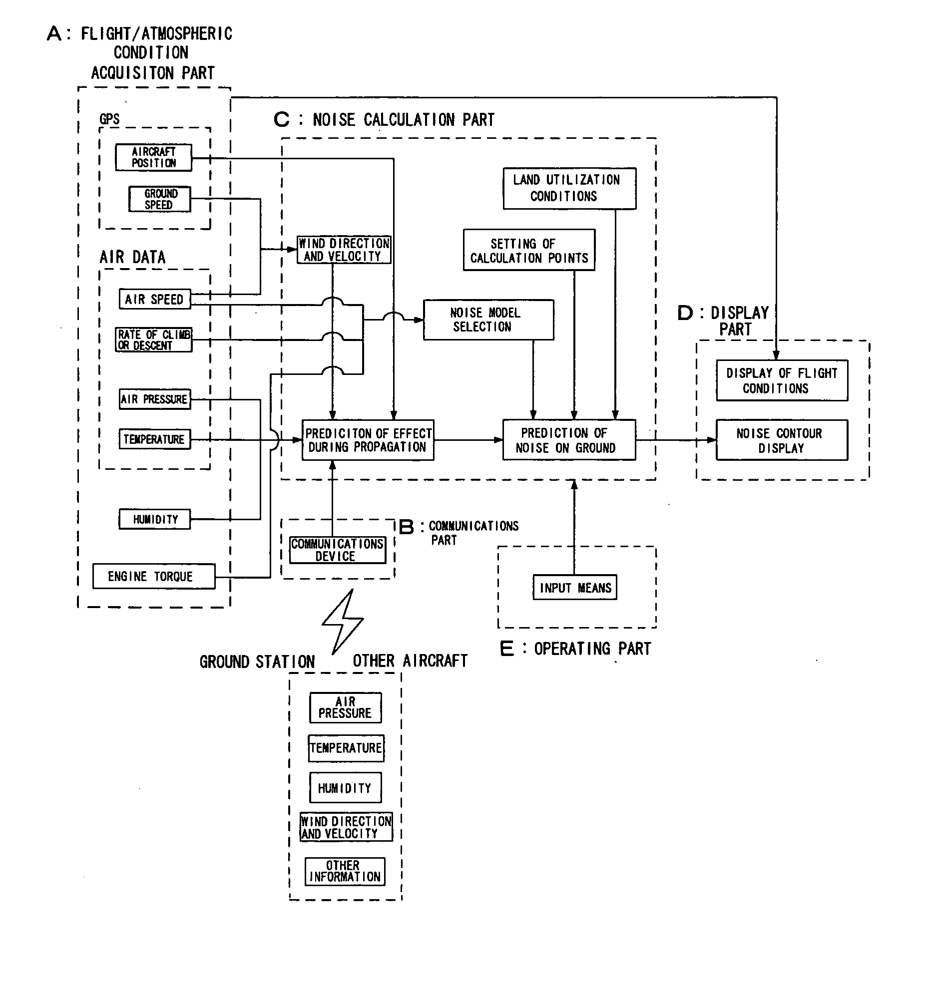
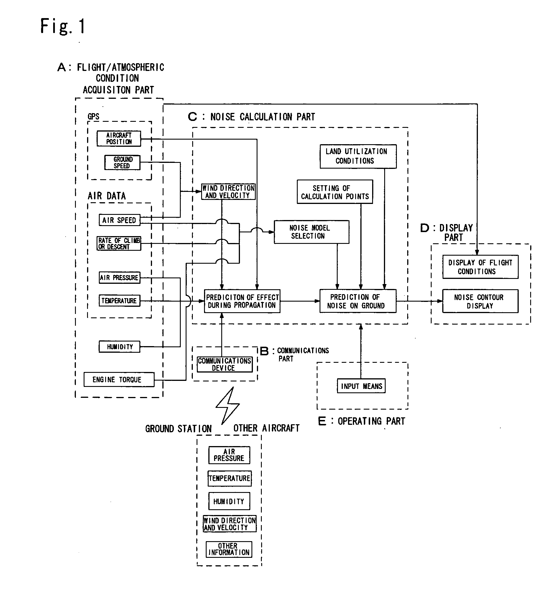
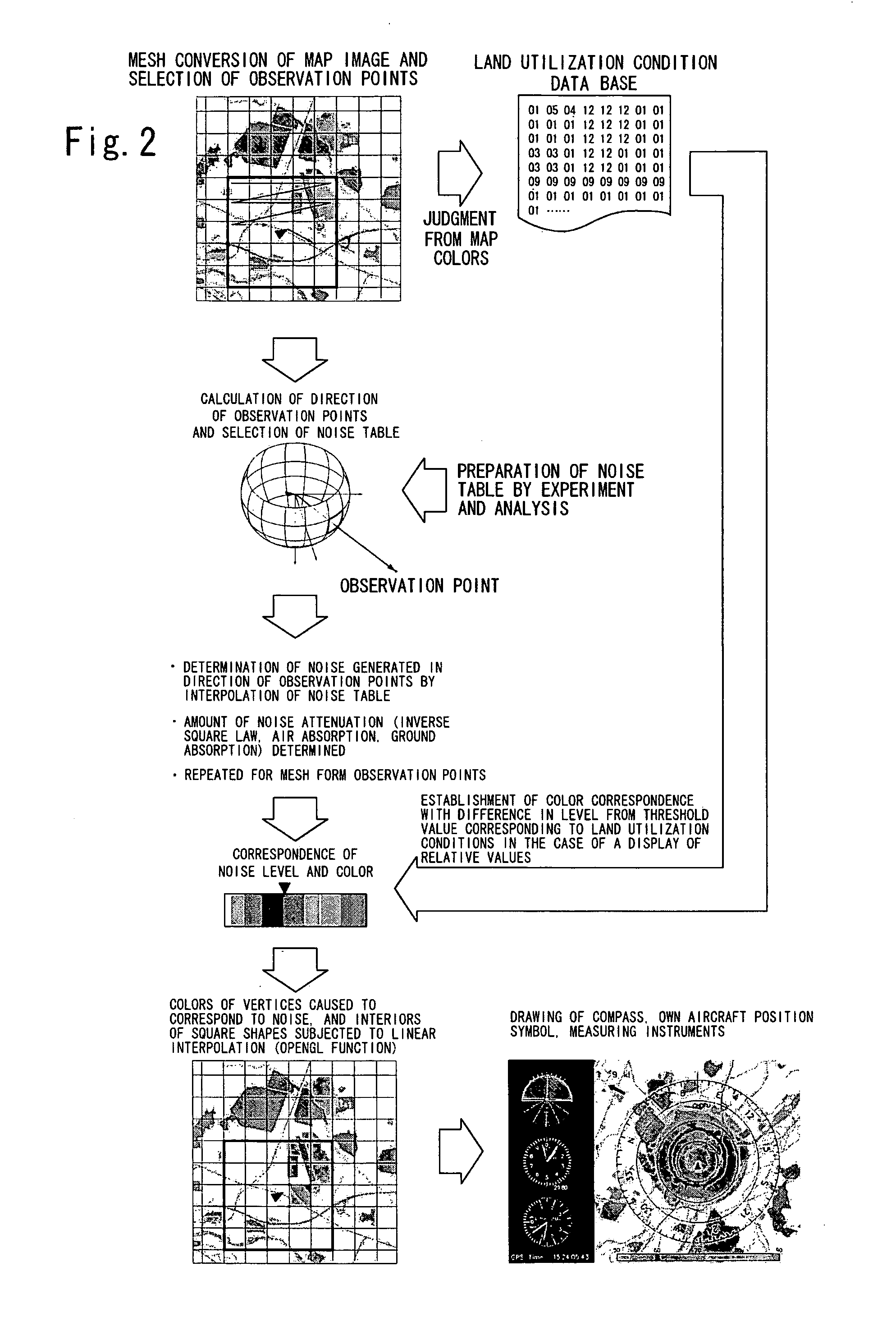
[0010] It is an object of the present invention to provide a system that provides support so that a pilot can perform a flight that reduces noise pollution, by calculating and displaying noise conditions on the ground on the basis of map information for the flight area in which facilities and the like are described, the wind direction and wind velocity in the flight area, environmental conditions such as the temperature and density of the atmosphere and the like, and noise generation data for the aircraft itself.

Problems solved by technology

This noise is generated from various types of sound sources such as the engine, propellers (rotors in the case of helicopters), landing gear and the like.
Furthermore, while noise generated by aircraft is being propagated through the atmosphere so that this noise reaches the ground, the noise is affected by environmental conditions at the location in question such as the wind direction, wind velocity, humidity and density of the atmosphere and the like since phenomena such as attenuation, diffraction and the like occur as a result of such atmospheric conditions.
In cases where the pilot is flying over familiar territory, the pilot can avoid places where noise pollution is a problem; however, in the case of areas that are being overflown for the first time, it is difficult for the pilot to obtain a sufficient grasp of the conditions in these areas.
In particular, a device which is mounted in aircraft, and which supports the reduction of noise pollution by displaying such information to the pilot has not yet been realized.
Likewise, however, these devices are not devices for supporting the pilot in performing a flight that takes noise conditions on the ground into account and reduces noise.

Method used


Image

  • Low-noise flight support system
  • Low-noise flight support system
  • Low-noise flight support system

Examples


example 1

[0092]FIG. 3 shows a flow chart of a prototype program. The operations of this program will be described in order.

[0093] 1. First, variable initialization is performed. Here, the setting of the flight area is performed. Next, the origin in the fixed ground coordinate system (NED), e.g., a specified point on the runway or the like, is determined. The runway dimensions are then input. Next, altitude information relating to the runway ground point used as the origin is input. Next, map information for the corresponding region is read out into a work area from the map information stored in the memory region, and the observation point mesh is set. Furthermore, land utilization conditions corresponding to this region are read in from the memory region, and are written into the work area.

[0094] 2. When this is completed, the display screen is initialized.

[0095] 3. Next, various selections are performed by operating the operating part. The reduction or enlargement magnification of the ma...


PUM


Abstract

It is an object of the present invention to provide a system that is used to provide support so that a pilot can perform flight operations that reduce noise pollution, by devising this system so that noise conditions on the ground are calculated and displayed on the basis of map information for the flight area in which facilities and the like are described, environmental conditions in the flight area such as the wind direction and wind velocity, or the temperature and density of the atmosphere, and noise generation data for the aircraft itself. The apparatus for supporting low-noise flight according to the present invention comprises means for estimating the noise generated by an aircraft using flight data such as the flight speed, the climb and descent rates, the engine power and the like of the aircraft, means for calculating the level at which the noise generated by the aircraft is propagated in the respective regions on the ground, and means for displaying the calculation results on a map in quantitative terms.

Description

BACKGROUND OF THE INVENTION [0001] 1. Field of the Invention [0002] The present invention relates to a system for providing support so that a pilot operating an aircraft can perform a flight that reduces noise pollution in areas where noise is especially likely to be a problem, such as hospitals, schools, residential areas, this support being provided by displaying the noise conditions on the ground to this pilot. [0003] 2. Description of the Related Art [0004] Aircraft perform flight operations while generating noise. This noise is generated from various types of sound sources such as the engine, propellers (rotors in the case of helicopters), landing gear and the like. Furthermore, while noise generated by aircraft is being propagated through the atmosphere so that this noise reaches the ground, the noise is affected by environmental conditions at the location in question such as the wind direction, wind velocity, humidity and density of the atmosphere and the like since phenomena...

Claims


Application Information

Patent Timeline
IPC IPC(8): G01C23/00
CPCG01C21/32G01C23/00
Inventor ISHII, HIROKAZUFUNABIKI, KOHEIOKUNO, YOSHINORIGOMI, HIROMI
Owner JAPAN AEROSPACE EXPLORATION AGENCY
Learn More