
Display device

a liquid crystal display and display device technology, applied in the direction of coupling device connections, instruments, optics, etc., can solve the problems of irregular fpc, high complex manufacturing processes, etc., and achieve regular and stable grounding, simplified grounding structure, and reduced manufacturing cost of lcd devices

Active Publication Date: 2006-05-25
SAMSUNG DISPLAY CO LTD
View PDF13 Cites 24 Cited by
  • Summary
  • Abstract
  • Description
  • Claims
  • Application Information

AI Technical Summary

Benefits of technology

[0011] The invention provides a receiving container for a display device capable of improving grounding characteristics of a circuit board.
[0012] The invention also provides a display device capable of improving grounding characteristics of a circuit board.
[0013] The invention also provides an LCD device capable of improving grounding characteristics of a circuit board.
[0019] Advantageously, manufacturing cost of the LCD device may be reduced and a grounding structure may be simplified. The FPC of the LCD device may be regularly and stably grounded, such that grounding characteristics may be improved. An ESD and an EMI generated from an FPC may be rapidly removed through the grounding structure.

Problems solved by technology

However, a g rounding method using the conductive double-sided adhesive tape has disadvantages in that manufacturing cost of the LCD device increases and manufacturing processes are complex.
A grounding method using the gap has further disadvantages in that an FPC is irregular and unstable.

Method used


Image

  • Display device
  • Display device
  • Display device

Examples


Embodiment Construction

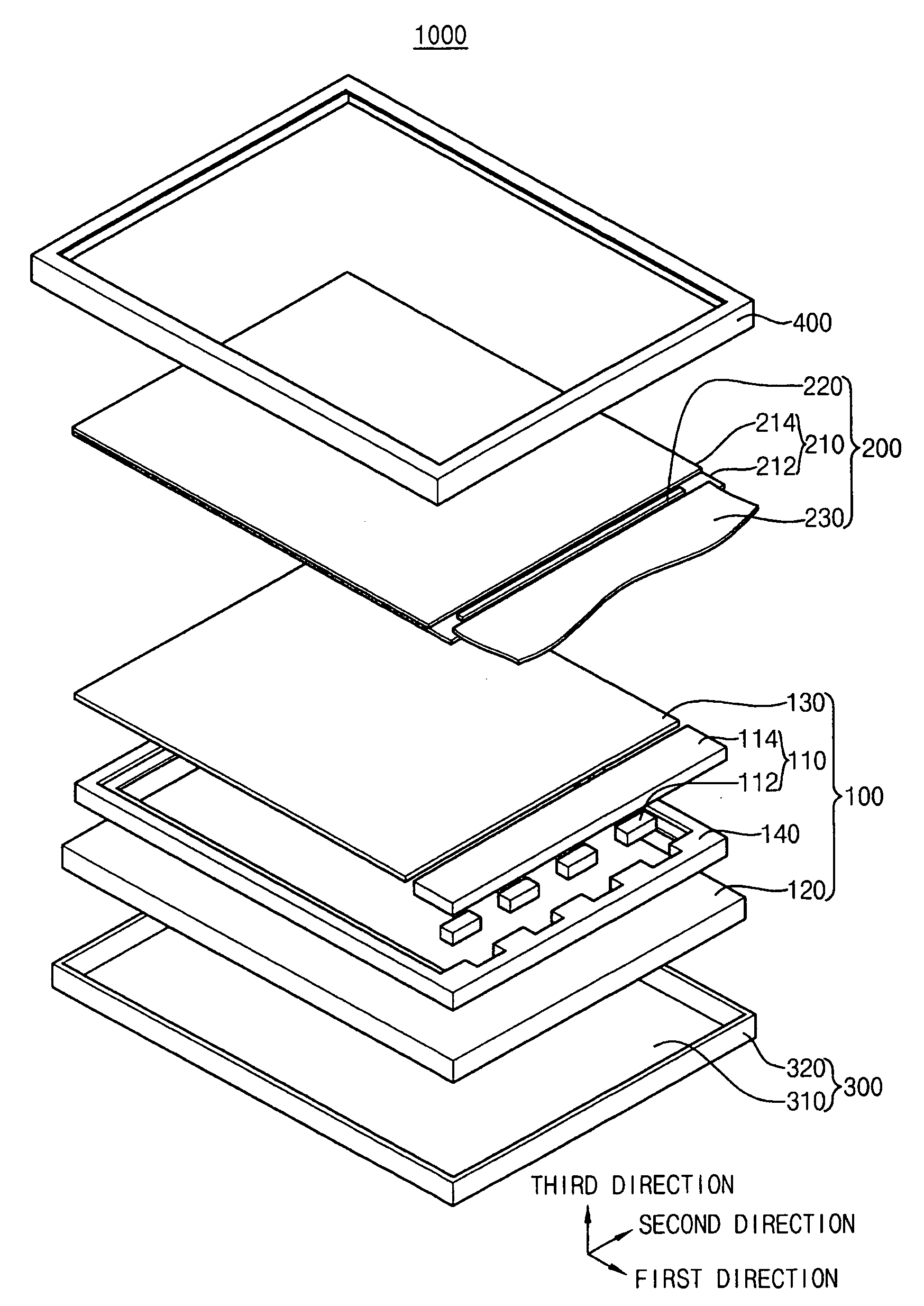
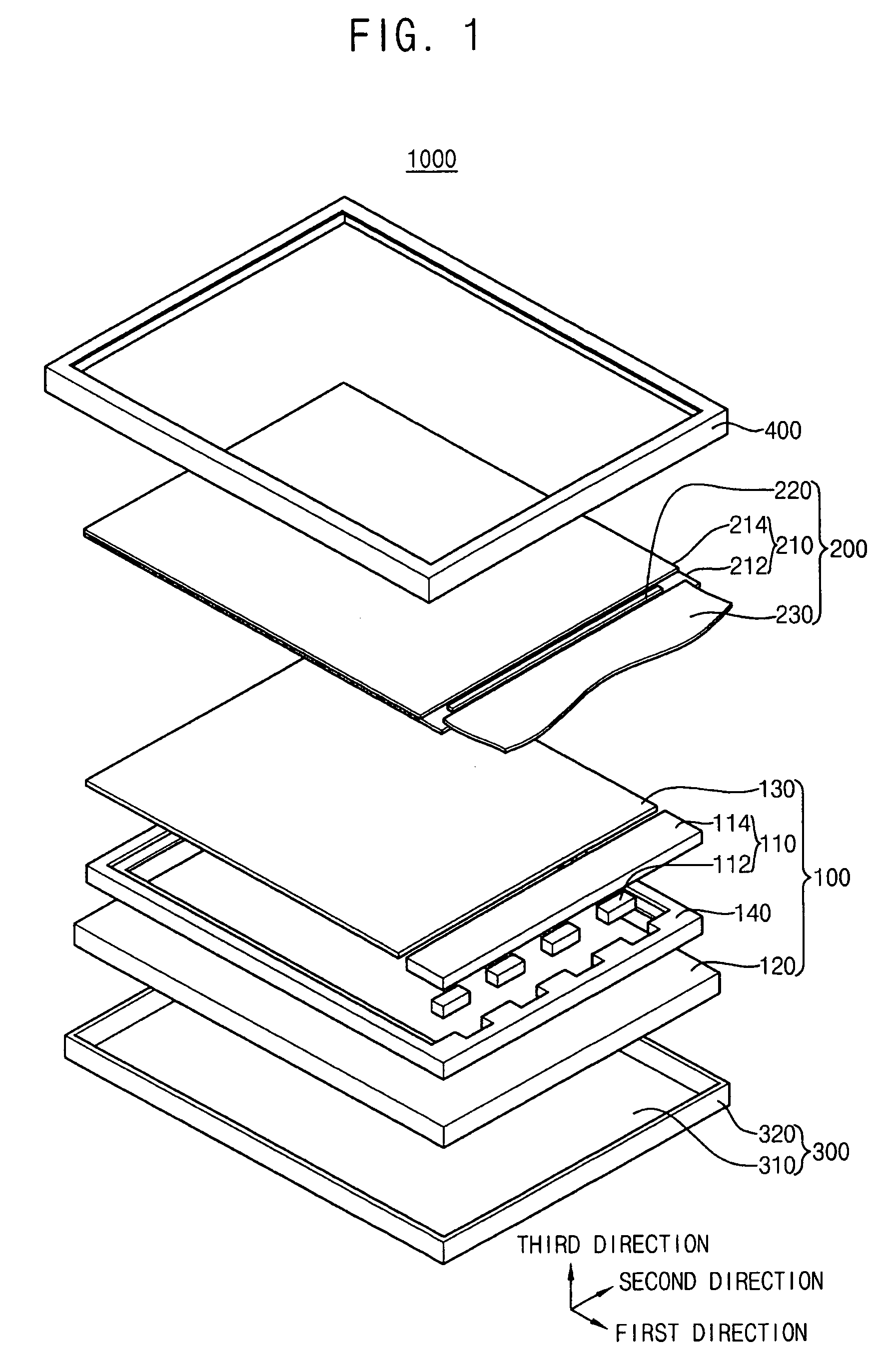
[0033] Exemplary embodiments will be described more fully hereinafter with reference to the accompanying drawings, in which embodiments of the invention are shown. The invention may, however, be embodied in many different forms and should not be construed as limited to the embodiments set forth herein; rather, these embodiments are provided so that this disclosure will be thorough and complete, and will fully convey the scope of the invention to those skilled in the art. Like reference numerals refer to similar or identical elements throughout.

[0034] It will be understood that when an element or layer is referred to as being “on” or “connected to” another element or layer, the element or layer can be directly on or connected to another element or layer or intervening elements or layers. In contrast, when an element is referred to as being “directly on” or “directly connected to” another element or layer, there are no intervening elements or layers present.

[0035] It will be underst...


PUM


Abstract

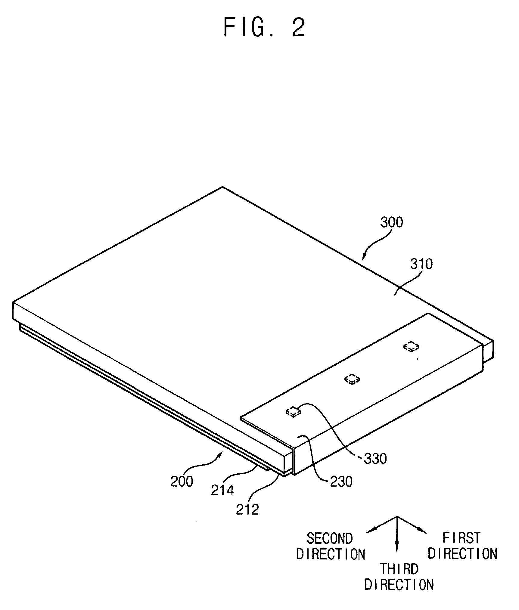
A receiving container for a display device includes a bottom plate, a sidewall and a grounding unit. The sidewall is extended from the bottom plate to define a receiving space. The grounding unit is integrally formed with the bottom plate. The grounding unit includes a grounding member that grounds a circuit board received in the receiving space. The circuit board includes a grounding electrode and the grounding member corresponds to the grounding electrode. The grounding member is formed on a rear surface of the bottom plate. The grounding member may include a protrusion or a projected portion having an elastic structure.

Description

[0001] This application claims priority to Korean Patent Application No. 2004-96269 filed on Nov. 23, 2004 and Korean Patent Application No. 2005-27162 filed on Mar. 31, 2005, and all the benefits accruing therefrom under 35 U.S.C. §119, the contents of which are herein incorporated by reference in their entireties.BACKGROUND OF THE INVENTION [0002] 1. Field of the Invention [0003] The invention relates to a receiving container for a display device and a liquid crystal display device having the receiving container. More particularly, the invention relates to a receiving container for a display device capable of improving grounding characteristics and a liquid crystal display device having the receiving container. [0004] 2. Description of the Related Art [0005] Generally, a liquid crystal display (LCD) device displays images using electrical and optical characteristics of liquid crystal installed therein. The LCD device has various advantages, for example, such as thin thickness, sma...

Claims


Application Information

Patent Timeline
IPC IPC(8): H01R12/00
CPCH01R13/2442H01R13/6471G02F1/133608H01R13/6585H01R13/6581H05K9/0067G02F1/133308G02F1/133314
Inventor JEE, AHN-HOLEE, KUN-BINKIM, DONG-HWANAHN, HYEONG-CHEOL
Owner SAMSUNG DISPLAY CO LTD
Learn More