
Automatic pipetting and analyzing device

a technology of automatic pipetting and analyzing device, which is applied in the direction of measurement device, material analysis by optical means, burettes/pipettes, etc., can solve the problems of inability to compact, inconvenient to operate, and inability to realize economical laboratory equipmen

Inactive Publication Date: 2006-05-25
CYBIO AG
View PDF5 Cites 12 Cited by
  • Summary
  • Abstract
  • Description
  • Claims
  • Application Information

AI Technical Summary

Benefits of technology

The invention is an automatic device for preparing and analyzing samples in microtitration plates. It has a work platform with areas for preparing samples and auxiliary devices, a mechanical table for positioning samples, and a pipetting head with a holder for microtitration plates. The device also has a coupling pin and a cutout for transmitting driving force to an inner passive slide. The technical effects of this invention include automation of pipetting and analysis of samples, improved accuracy and efficiency, and reduced human error.

Problems solved by technology

The technical problem addressed in this patent is the lack of efficient and cost-effective laboratory equipment that enables automatic preparation and analysis of samples without requiring manual transfer between devices. Existing solutions involve complex mechanisms or slow temperature regulation times.

Method used


Image

  • Automatic pipetting and analyzing device
  • Automatic pipetting and analyzing device
  • Automatic pipetting and analyzing device

Examples


Embodiment Construction

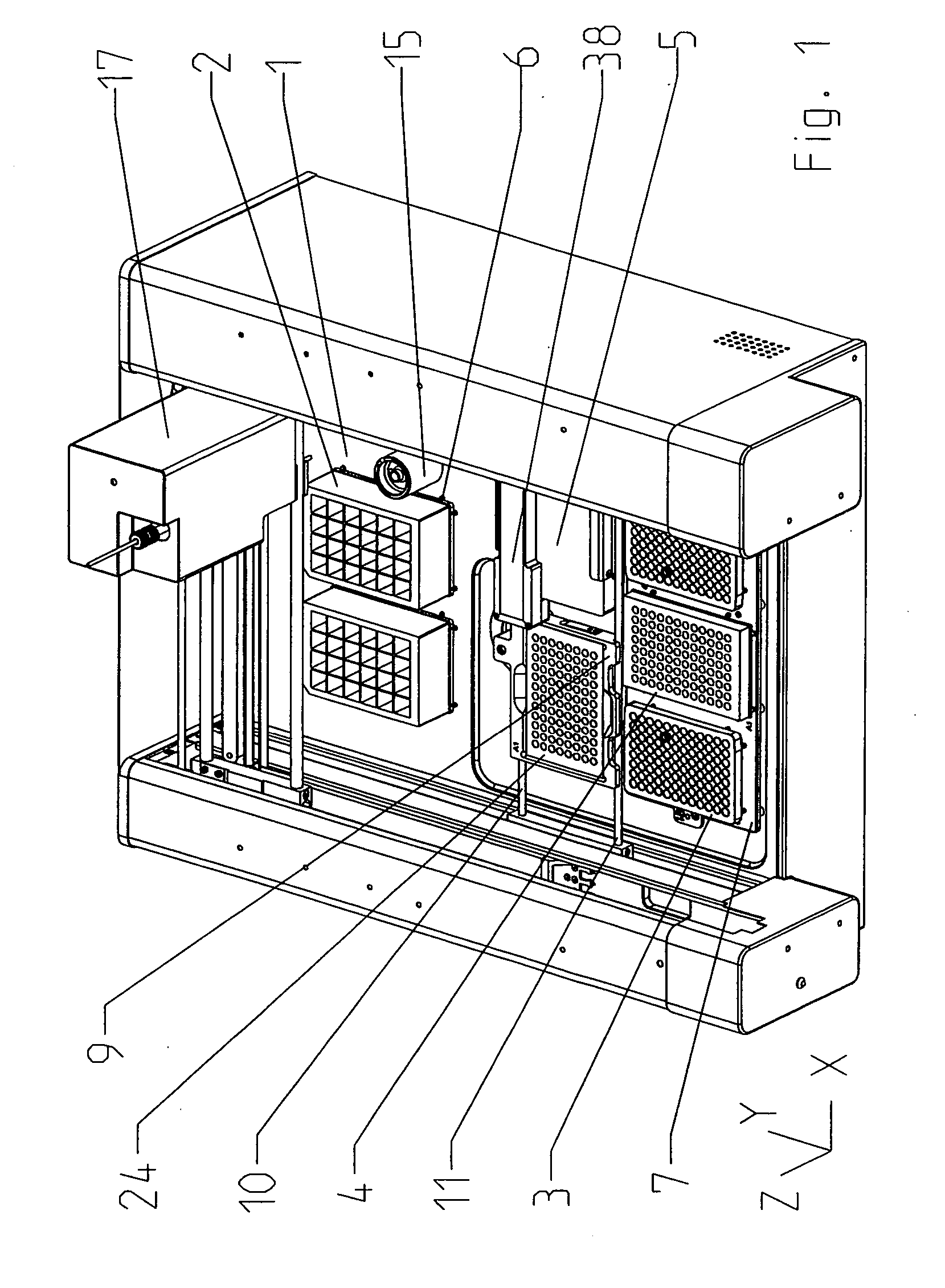
[0032]FIG. 1 shows a device according to the invention without the cover that usually closes the device. The drawing showing the device in the opened state allows the interior of the device to be seen, particularly the work platform 1 on which are provided positioning areas in which are arranged auxiliary devices that are necessary for the automatic operating sequence of the device. Usually, auxiliary devices of this kind are supply vessels 2, tip magazines 3, additional microtitration plates 4 containing the material to be examined, an incubator 5, or a rinsing device 15. Other auxiliary devices used for analysis can be magnetic holders for magnetic particle handling or devices for carrying out vacuum extraction steps.

[0033] In the device construction shown herein, two positioning areas are provided directly on the work platform 1 for deep well blocks serving as supply vessels 2. Deep well vessels of this kind make it possible to reserve different amounts of various liquids with r...


PUM


Abstract

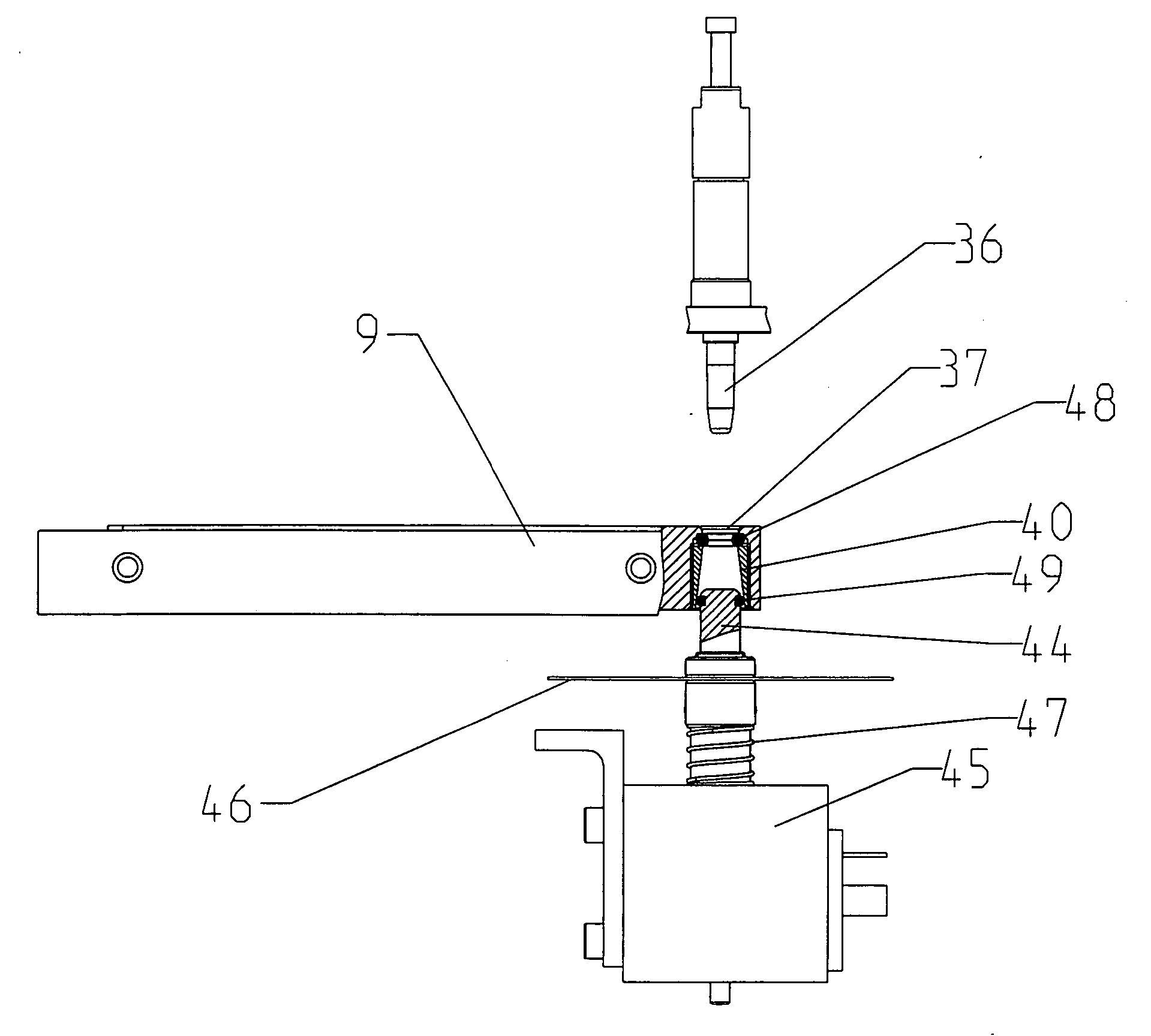
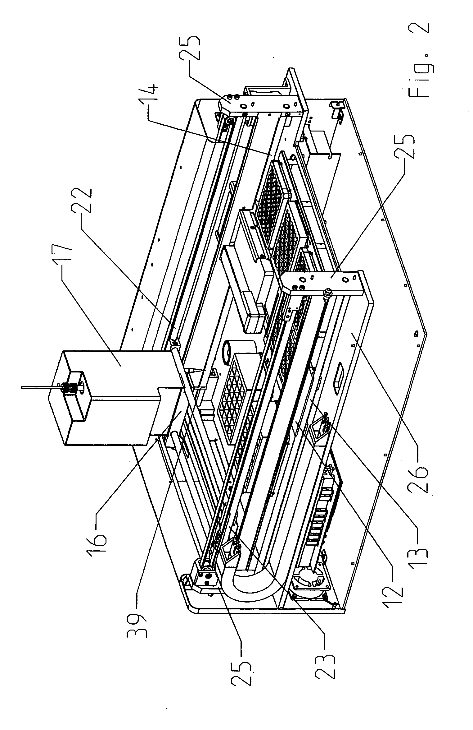
An automatic pipetting and analyzing device for the preparation and analysis of samples in the wells of a microtitration plate has a work platform on which positioning areas for auxiliary devices and a movement area for the sample plate are provided, a passive mechanical table without its own drive unit, the sample plate lying within the inner passive slide of the passive mechanical table, and an active mechanical table which is arranged above the passive mechanical table and by which a pipetting head can be moved in X-Y direction over the work platform in order to extract, transport and dispense liquids by at least one pipetting channel and in order to displace the sample plate by a coupling connection with the inner passive slide, for example, to place the sample plate in an incubator or to position it with the individual wells in an analysis device.

Description


Claims


Application Information

Patent Timeline
Owner CYBIO AG
Learn More