
Roof module for a motor vehicle and process for producing same

a technology for motor vehicles and roof modules, applied in the field of roof modules, can solve the problems of high cost of glass fiber mats, time-consuming and complicated production of multi-layer roof modules based on honeycomb structures, and the positioning of honeycomb layers within negative molds used for pressing processes, etc., and achieves low total weight and high stiffness.

Inactive Publication Date: 2006-05-25
WEBASTO AG
View PDF14 Cites 3 Cited by
  • Summary
  • Abstract
  • Description
  • Claims
  • Application Information

AI Technical Summary

Benefits of technology

[0008] Accordingly, a primary object of this invention is to provide a roof module which has high stiffness and low total weight.
[0009] A further object of the invention is to create a process for producing such a roof module that is less time-consuming and more economical.
[0010] One important aspect of the invention is that the roof module for a motor vehicle with an outside roof skin and layers of composite material located on the vehicle interior side, beginning from the outside skin, has the following layer structure at least on the planar portion: a first fiber-containing layer produced using the long-fiber injection process and a carrier layer of stiffening material which is preferably honeycombed. By combining a layer based on the LFI production process with a honeycomb, sandwich-like carrier layer, the advantages of the two techniques underlying these layers are combined with one another. On the one hand, the difficult and time-consuming handling of glass fiber mats as was necessary in the past in honeycomb carrier layers as a layer between the PU layer and the carrier layer, and on the other, the trade-offs which had to be made for the total weight and the stiffness according to the LFI process are eliminated.

Problems solved by technology

Production of multilayer roof modules of this type based on a honeycomb structure is time-consuming and complicated since generally glass fiber mats which extend on either side of the honeycomb layer are difficult to handle.
Furthermore, these glass fiber mats are expensive as compared to glass fibers as are used in the LFI production process.
In addition, positioning of the honeycomb layer within a negative mold which is used for carrying out the following pressing processes is generally complex and time-consuming.

Method used


Image

  • Roof module for a motor vehicle and process for producing same
  • Roof module for a motor vehicle and process for producing same
  • Roof module for a motor vehicle and process for producing same

Examples


first embodiment

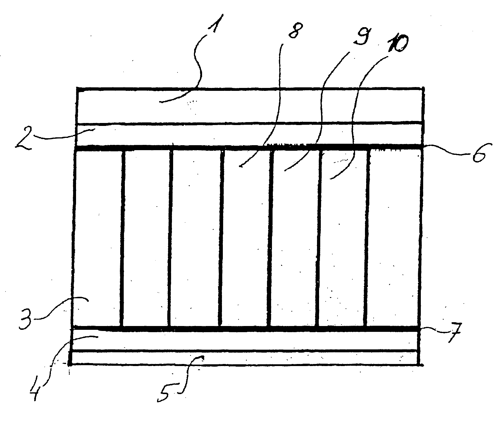
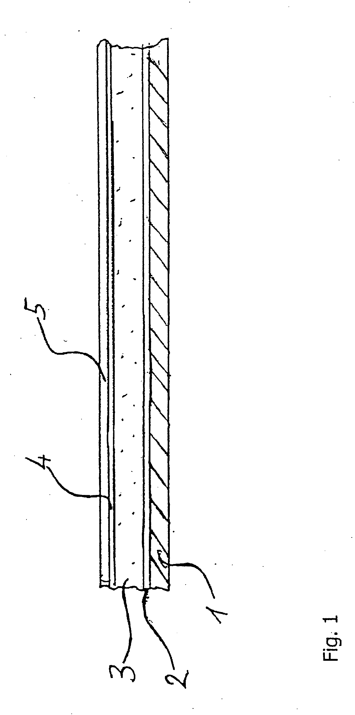
[0035]FIG. 1 shows the layered structure of a roof module which comprises an outside roof skin 1, a first glass-fiber containing layer 2 produced using the LFI process, a preferably honeycomb carrier layer 3 of stiffening material, such as PHC, a second glass fiber-containing layer 4 based on the LFI process, and a laminated layer 5 for a termination of the layered structure in the vehicle interior, which termination acts has a visually attractive appearance.

[0036] According to the production process, an outside roof skin is inserted into a negative mold of a pressing device, and by means of the LFI process, is covered with a layer 2 which contains PUR-wetted glass fibers and which are blown by means of compressed air into the negative mold. The glass fibers are preferably 10-100 mm long.

[0037] The honeycomb carrier layer 3, is preferably made of the stiffening material PHC and is placed on the first layer 2 which contains the glass fibers. Then, a second glass-fiber containing lay...

second embodiment

[0039] In order to reduce the unnecessarily high consumption of PUR, as is shown in FIG. 3, according to the layered structure of the roof module of the invention, the carrier layer 3 is covered with a blocking nonwoven material 6, 7, on the top and bottom sides, so that the PUR penetrates only to a predefined penetration depth into the honeycomb structure to ensure adhesion of the glass fiber-containing layers 2, 4 to the carrier layer. The glass fibers which are contained in the glass fiber-containing layers 2, 4 are kept by the blocking nonwoven material 6, 7 from penetrating into the honeycomb structure. In this way, the required amount of glass fiber and amount of PUR are reduced, and thus, weight and money are saved.

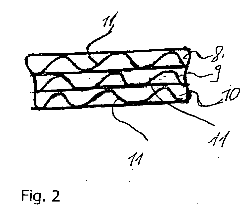
[0040]FIG. 4 shows a schematic cross section of a third embodiment of the layered structure of the roof module as in accordance with the invention. The layered structure according to the third embodiment differs from the layered structure according to the second em...


PUM

PropertyMeasurementUnit
thicknessaaaaaaaaaa
thicknessaaaaaaaaaa
temperatureaaaaaaaaaa

Abstract

A roof module for a motor vehicle with an outside roof skin and layers of composite materials located on the vehicle interior side of at least planar portions of the roof skin and a process for producing such a module. The layers on the vehicle-interior side are arranged in the order, beginning from the outside roof skin, of a first fiber-containing layer produced using the long-fiber injection process, and a carrier layer of stiffening material.

Description

CROSS-REFERENCE TO RELATED APPLICATION [0001] This application is a division of co-pending U.S. patent application Ser. No. 10 / 392,384.BACKGROUND OF THE INVENTION [0002] 1. Field of the Invention [0003] The invention relates to a roof module for a motor vehicle with an outside roof skin and layers of composite materials located on the vehicle interior side and a process for producing a multilayer roof module for a motor vehicle with an outside roof skin and layers of composite materials located on the vehicle interior-side. [0004] 2. Description of Related Art [0005] Roof modules as are known, for example, from published. European Patent Application EP 0 960 803 A2, constitute motor vehicle roofs which have been produced separately from the motor vehicle body and which are made sandwich-like with a roof skin and an underlying plastic layer made, for example, of foam plastic. [0006] Published European Patent Application EP 0 995 667 A1 discloses a roof module as a composite component...

Claims


Application Information

Patent Timeline
Patent Type & Authority Applications(United States)
IPC IPC(8): B27N1/00D21J3/00B32B17/04B62D25/06B62D29/04
CPCB32B17/04B62D25/06Y10T428/24355Y10T428/24149B62D29/04
Inventor STROHMAVR, PETERDICHTL, MATTHIAS
Owner WEBASTO AG
Learn More