
High watt density thermoelectrics

a thermoelectric module and high-watt density technology, applied in the field of high-watt density thermoelectrics, can solve the problems of ineffective solutions produced by existing manufacturing techniques, and achieve the effect of reducing the disadvantages and problems of manufacturing thermoelectric modules with thin thermoelectric elements, and being easy to process

Inactive Publication Date: 2006-05-25
MARLOW INDUSTRIES
View PDF20 Cites 21 Cited by
  • Summary
  • Abstract
  • Description
  • Claims
  • Application Information

AI Technical Summary

Benefits of technology

[0006] In accordance with the present invention, the disadvantages and problems associated with manufacturing thermoelectric modules with thin thermoelectric elements have been substantially reduced or eliminated. In particular, a method is provided which allows manufacturing of thin thermoelectric elements by coupling the elements to a stiff backing so the thermoelectric material may be more easily processed.
[0010] Technical advantages of certain embodiments of the present invention include enabling production of thermoelectric elements which are thinner than traditional manufacturing methods are capable of achieving. Some thermoelectric materials become brittle or break when thinned past a threshold thickness. Coupling the thermoelectric material to a stiff backing provides support to the thermoelectric material and allows the thermoelectric material to be thinned to a point beyond which it may have been expected to break without the stiff backing.
[0011] Other technical advantages of certain embodiments of the present invention include using a stiff backing which is electrically and thermally conductive. In this manner the thermoelectric material does not need to be removed from the stiff backing, but may be diced into thermoelectric elements while still coupled to the stiff backing. This may result in thermoelectric elements (thermoelectric material and stiff backing) which are sufficiently large to be assembled into thermoelectric modules utilizing traditional systems or methods such as vide loading or pick-and-placing.

Problems solved by technology

As cooling applications progressively require smaller thermoelectric devices, existing manufacturing techniques have been unable to produce effective solutions.

Method used


Image

  • High watt density thermoelectrics
  • High watt density thermoelectrics
  • High watt density thermoelectrics

Examples


Embodiment Construction

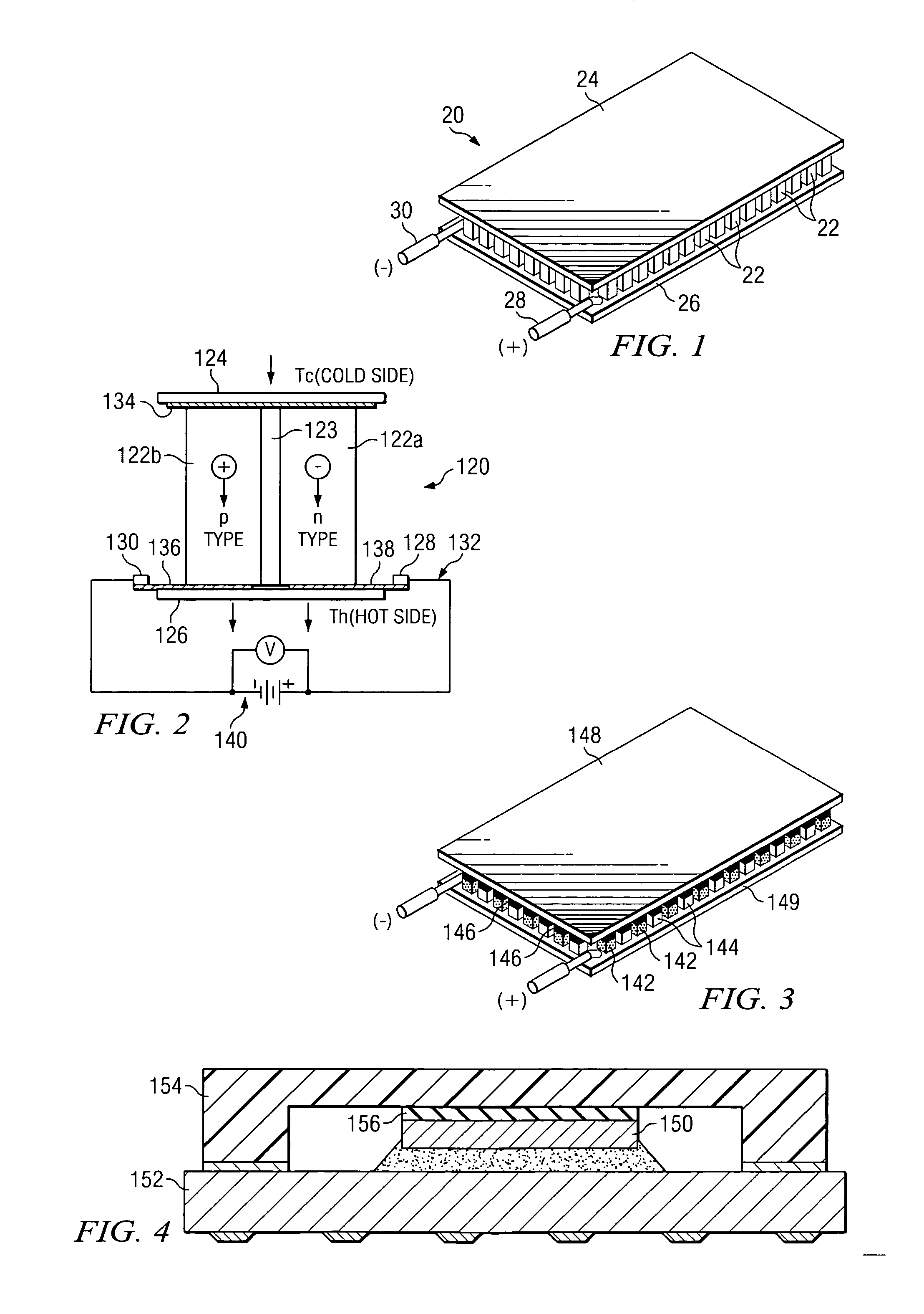
[0024]FIG. 1 illustrates a thermoelectric device 20 including a plurality of thermoelectric elements 22 disposed between a cold plate 24 and a hot plate 26. Electrical connections 28 and 30 are provided to allow thermoelectric device 20 to be electrically coupled with an appropriate source of DC electrical power.

[0025] Thermoelectric device 20 may be used as a heater, cooler, electrical power generator, and / or temperature sensor. If thermoelectric device 20 were designed to function as an electrical power generator, electrical connections 28 and 30 would represent the output terminals from such a power generator operating between hot and cold temperature sources.

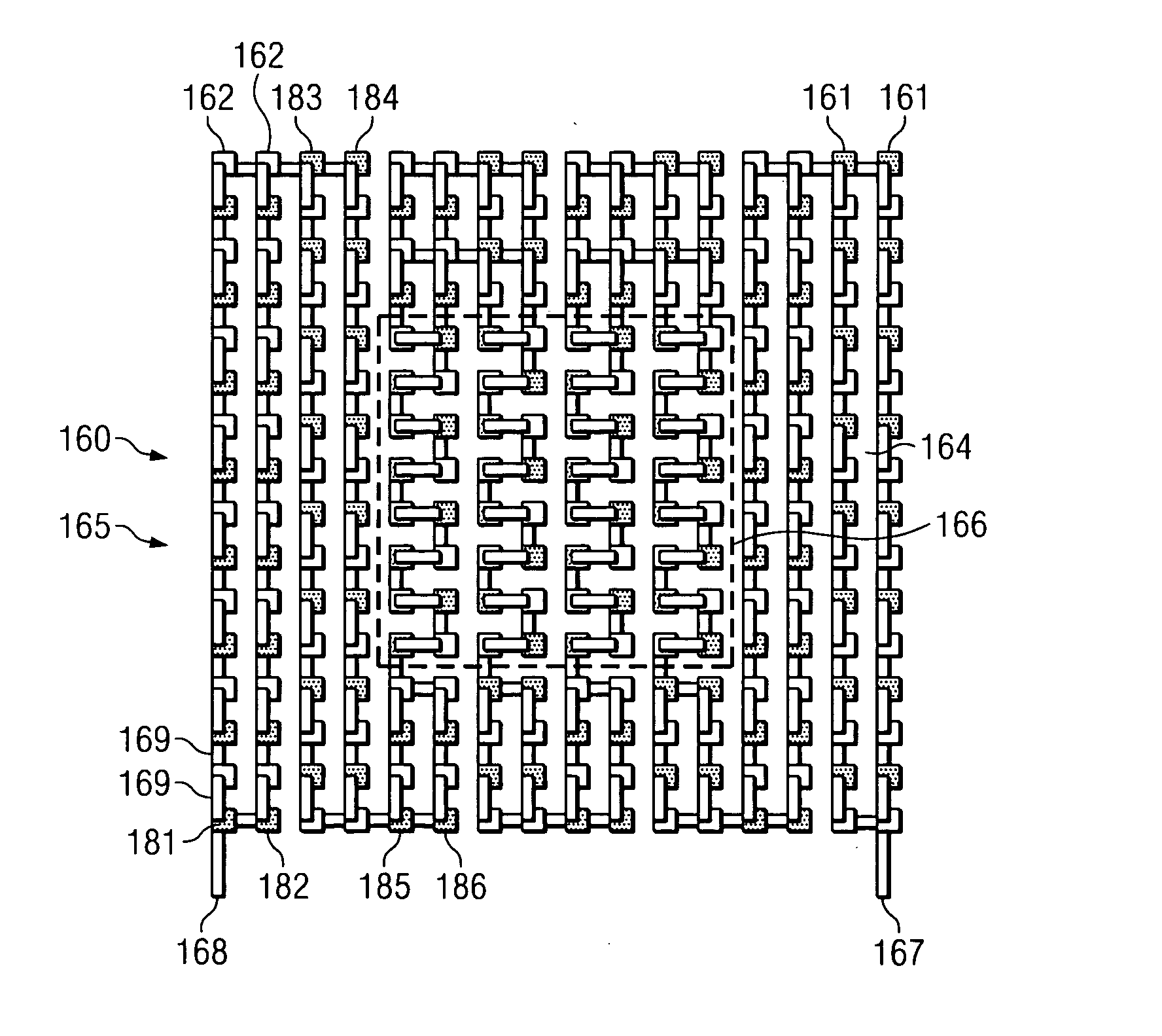
[0026]FIG. 2 is a schematic representation of an electrical circuit 132 of a single stage thermoelectric device 120. Electrical circuit 132 may also be incorporated into thermoelectric elements or thermocouples to convert heat energy into electrical energy. Electrical circuit 132 generally includes two or more thermoelectr...


PUM


Abstract

In accordance with one embodiment of the present invention, a method of manufacturing a thermoelectric device is disclosed. The method includes forming a wafer of thermoelectric material and coupling the wafer to a stiff backing such that a bottom side of the wafer faces the stiff backing and a top side of the wafer faces away from the stiff backing. The method also includes reducing a thickness of the wafer by removing a portion of the wafer from the top side, and dicing the wafer into a plurality of blocks. At least a portion of the plurality of blocks are then coupled with a permanent substrate.

Description

TECHNICAL FIELD OF THE INVENTION [0001] This invention relates in general to a system and method for manufacturing thermoelectric elements, and more particularly to high watt density thermoelectrics. BACKGROUND OF THE INVENTION [0002] The basic theory and operation of thermoelectric devices has been developed for many years. Presently available thermoelectric devices used for cooling typically include an array of thermocouples which operate in accordance with the Peltier effect. Thermoelectric devices may also be used for heating, power generation and temperature sensing. [0003] Thermoelectric devices may be described as essentially small heat pumps which follow the laws of thermodynamics in the same manner as mechanical heat pumps, refrigerators, or any other apparatus used to transfer heat energy. A principal difference is that thermoelectric devices function with solid state electrical components (thermoelectric elements or thermocouples) as compared to more traditional mechanica...

Claims


Application Information

Patent Timeline
IPC IPC(8): H01L35/30H01L35/28
CPCH01L35/32H01L35/34H10N10/01H10N10/17
Inventor BIERSCHENK, JAMES L.MOCZYGEMBA, JOSHUA E.AYDELOTT, TRACY H.
Owner MARLOW INDUSTRIES
Learn More