Air conducting channel

Inactive Publication Date: 2006-05-25
MANN HUMMEL GMBH
View PDF8 Cites 12 Cited by
  • Summary
  • Abstract
  • Description
  • Claims
  • Application Information

AI Technical Summary

Benefits of technology

[0010] Another object of the invention is to provide an air conducting channel which avoids the aforementioned drawbacks.
[0028] The channel section according to the invention may be used to adsorb unburned hydrocarbons, e.g., in an air conducting channel for the intake air of an internal combustion engine, or in an air conducting channel used to supply air to the interior of an automotive vehicle. If it is used in the air conducting channel for the intake air, the channel section according to the invention serves to reduce hydrocarbon emissions when the engine is stopped in order to meet the applicable limits and requirements imposed on the automobile manufacturer. If it is used as an air conducting channel to supply air to the interior of an automotive vehicle, the channel section serves rather to reduce noxious gases and odors before they can reach the interior of the vehicle and the passengers.

Problems solved by technology

In connection with the above-described SULEV / ULEV problem, the disadvantage, however, is that hydrocarbons present in the intake manifold of an internal combustion engine, for example, may escape into the environment when the engine is stopped.
Drawbacks in all of these solutions include the high complexity involved in their production, the considerable pressure loss which may occur across the adsorbent filter, and the need for special adaptation of the housing and air conducting channels to the adsorbent elements.

Method used


Image

  • Air conducting channel
  • Air conducting channel

Examples


Embodiment Construction

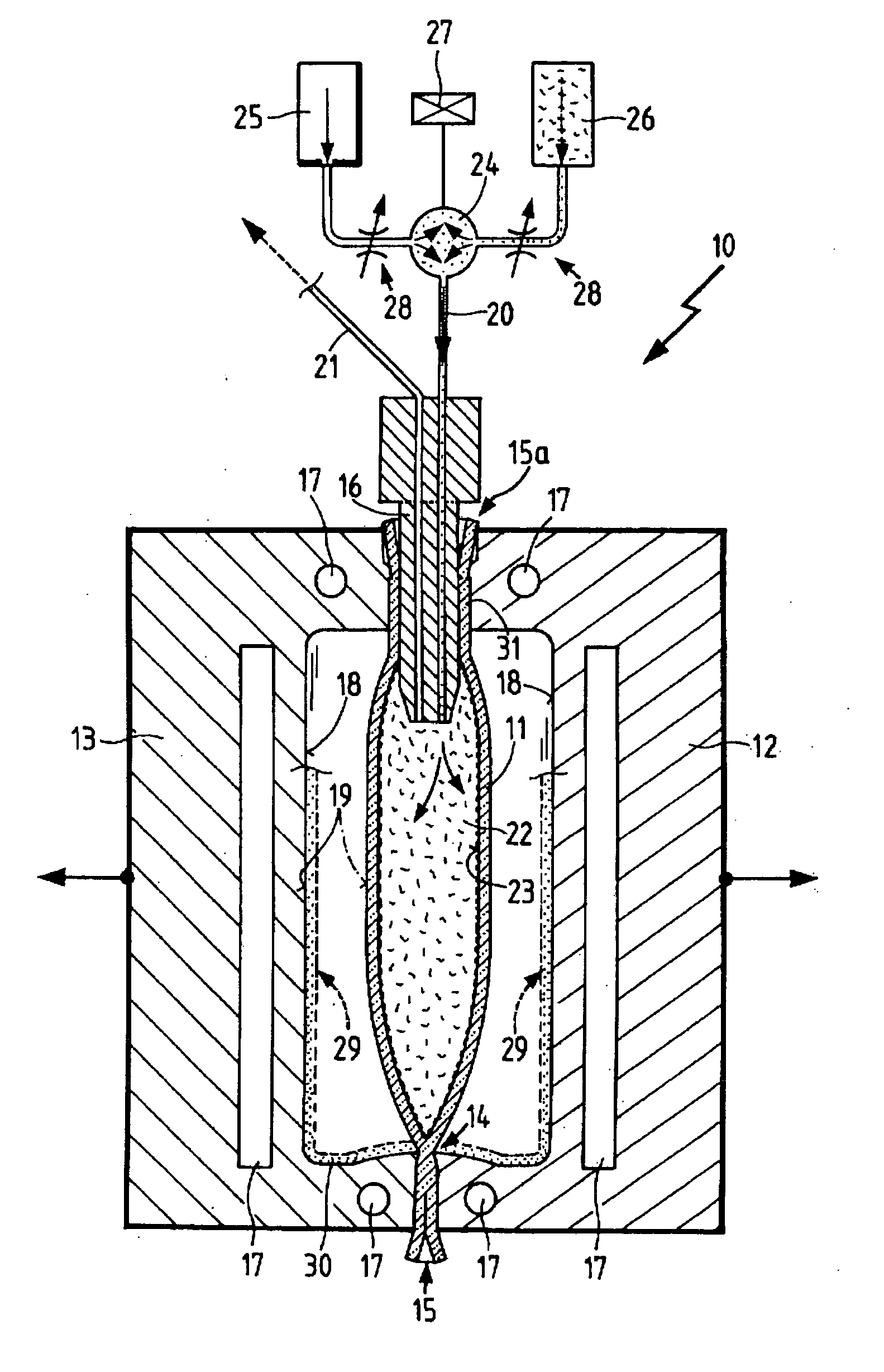
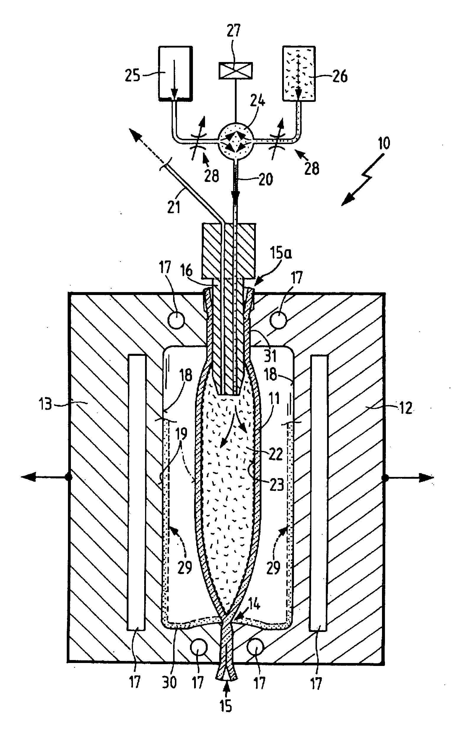
[0031] The single FIGURE shows a blow molding unit 10 with a preform 11 in the form of a tube which was introduced directly into the blow molding unit 10 of an extrusion machine (not shown). As a result, the preform 11 still has a very high temperature and relatively low viscosity, that is to say, the walls are still soft and deformable. The preform is clamped between two mold sections 12 and 13, such that in the lower region where the mold sections 12, 13 meet, a crimped area 14 results, where the tubular synthetic resin material material of the preform 11 is joined again, and such that the excess thereof, the so-called parison waste 15, is pinched off the preform 11. In the upper region of the mold sections 12, 13, the preform 11 is pressed by the mold sections 12, 13 against an injector nipple 16 extended into the interior of the preform 11, such that excess parison waste 15a of the preform 11 is again pinched off.

[0032] Cooling channels 17 are disposed in the mold sections 12, ...


PUM

PropertyMeasurementUnit
Lengthaaaaaaaaaa
Timeaaaaaaaaaa
Pressureaaaaaaaaaa

Abstract

A channel for conducting a gaseous medium, particularly an air conducting channel for an internal combustion engine, having at least one channel section that is produced in an extrusion blow molding process. The blow-molded channel section has adsorption particles on its inside walls, which are attached in an interlocked manner to the inside wall of the channel section in the blow molding process.

Description

BACKGROUND OF THE INVENTION [0001] The invention relates to an air conducting channel in accordance with the species of claim 1. The invention further relates and to a process for manufacturing an air conducting channel of this type. [0002] An essential goal in the design of modern internal combustion engines is to reduce emission of harmful substances. Until now, the development activities have focused primarily on optimizing the exhaust emission control system. Modern exhaust emission control systems meanwhile achieve conversion rates for harmful substances greater than 97%. [0003] Increasing air pollution has led most countries to limit emissions and to continue to tighten these limits. To assure reproducibility and comparability, various test methods, ratings and limits have been developed. In the United States, for example, the limits include the categories ULEV (Ultra Low Emission Vehicle), SULEV (Super Ultra Low Emission Vehicle) and the currently strictest category, PZEV (Pa...

Claims


Application Information

Patent Timeline
IPC IPC(8): B01D53/02B29C35/16B29C37/00B29C49/04B29C49/24B29C49/46B29C49/48B29D23/00F02M35/10F16L9/12F24F13/02
CPCB29C35/16B29C37/0025B29C49/04B29C49/24B29C49/46B29C49/4823B29C2049/027B29C2049/2404B29K2077/00B29L2009/005B29L2023/22B29L2031/30F02M35/02F02M35/10144F02M35/10281F02M35/10321F02M35/10347B29C2949/3076
Inventor HEILMANN, TANJAPFEIFFER, FRANKSPENNEMANN, ALRUNFRANZ, ANDREAS
Owner MANN HUMMEL GMBH
Why Eureka
Try Eureka