
Enterprise factory control method and system

a factory control and enterprise technology, applied in the field of manufacturing execution systems, can solve the problems of consuming a great deal of information, preventing any supplier to the customer from achieving an overall view of manufacturing locations and processes, and unable to meet the needs of customers,

Inactive Publication Date: 2006-05-18
SERVICENOW INC
View PDF6 Cites 59 Cited by
  • Summary
  • Abstract
  • Description
  • Claims
  • Application Information

AI Technical Summary

Benefits of technology

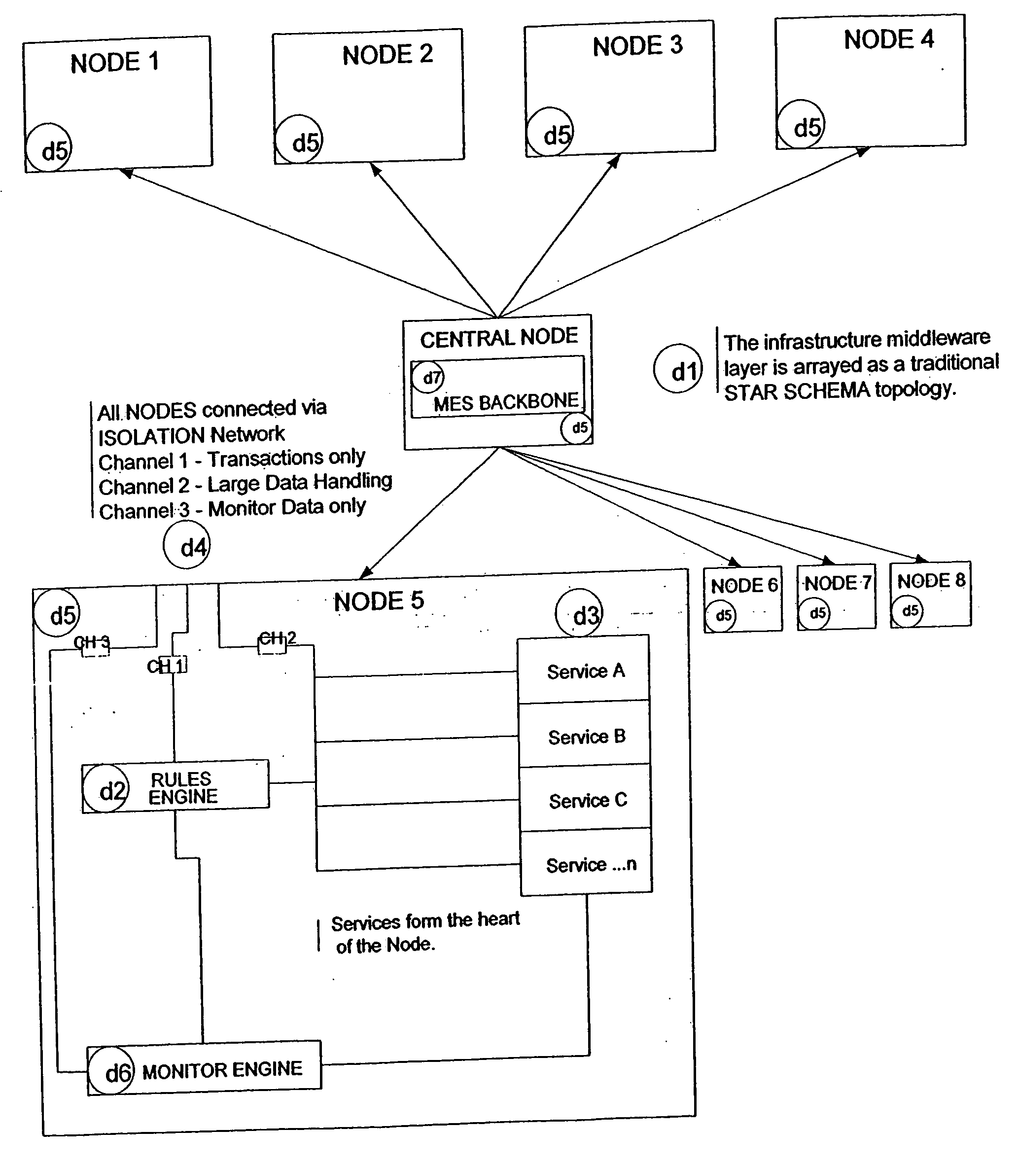
[0012] The invention also provide a system which integrates customer / supplier / vendor manufacturing: one in which a simple and singular definition of a product's lifecycle is created, and then applied to a flexible set of manufacturing assets, capable of tailored real-time behavior, and integrated to the degree necessary for proper monitoring and control, as well as ongoing customer visibility to work in process.

Problems solved by technology

This diversity of behavior and systems make it difficult for the customer to ever see an integrated view of their product during manufacturing.
More importantly, it prevents any supplier to the customer from achieving an overall view of manufacturing locations and processes, from either a monitoring or control point of view.
This heterogeneous collection of customers, suppliers and vendors produces and consumes a great deal of information that needs to flow up, down and across the supply network.
With a diverse set of processes and systems involved, the resulting integration nightmare causes lengthy time-to-market for the customer's products, especially if any customization is required at any point in the manufacturing process.
In addition, there is little to no flexibility available to the supplier in their choice and use of vendor production facilities for either specialization or capacity variability.
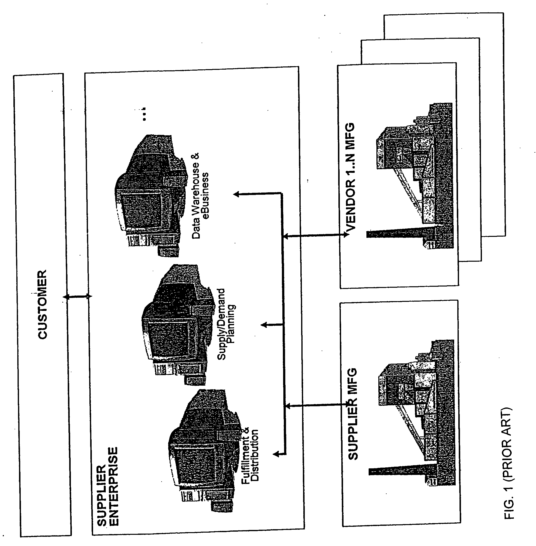
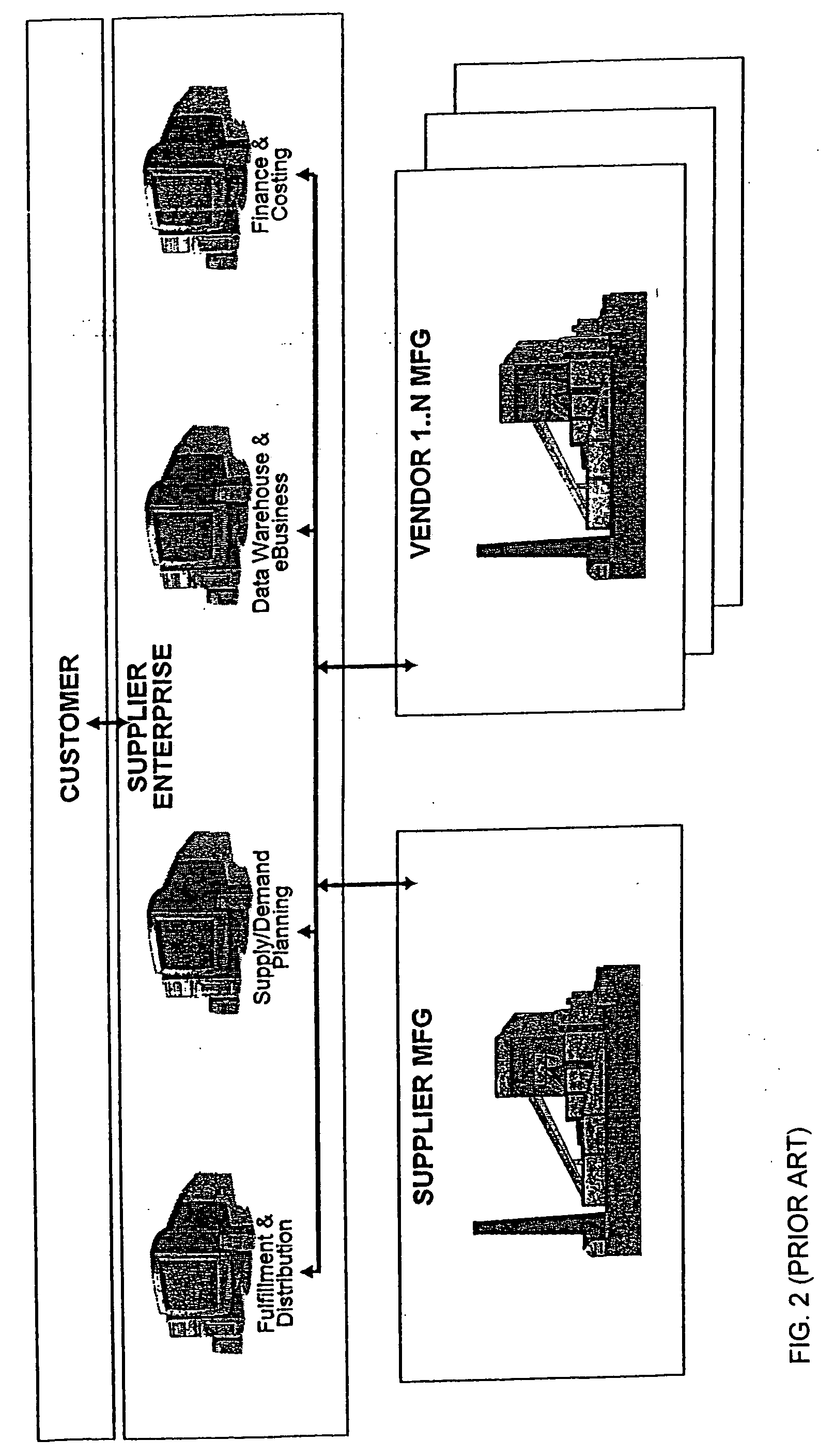
This integration is further complicated by the need for timely event and characteristic information from each of the manufacturing stages' execution systems to be fed to the supplier enterprise systems, such as order processing and fulfillment, financial management, logistics planning and product / process engineering as illustrated in FIG. 1.
Numerous different execution systems drive the need for equally numerous interfaces, adding complexity in upkeep, reduced flexibility, and often inaccuracies in data and synchronization.

Method used


Image

  • Enterprise factory control method and system
  • Enterprise factory control method and system
  • Enterprise factory control method and system

Examples


example

Semiconductor Industry

[0131] Service Provider knows that each customer uses SAP as an enterprise system and therefore needs to have a lot identifier that is constrained to ten digits. In addition, Service Provider knows that the customer wants to track the lots for its full lifecycle without change for the parent lot and that the child lots should have a visibly obvious relationship to the parent lots. In addition, Service Provider knows that the customer wants to have the possibility of the lot being processed at a multiplicity of sites yet avoid any duplication of lot identification for a minimum of five years and not contain any false information. Service Provider also knows that the vendors must split and merge lots in real time and therefore cannot accept a system of centralized control.

[0132] To this end, Service Provider creates a Universal Lot Label with the following alphanumeric lot naming scheme set forth in FIG. 17:

[0133] Code Meaning

[0134] S:

[0135] The purpose of t...


PUM


Abstract

A system, method, service and media for managing both supplier-owned and non-owned manufacturing asset types utilizing a supplier model of a product which goes across the manufacturing asset types. The invention maps the model to instances of the asset types and uses a network to control and monitor the assets. The monitoring and control occur according to the model, rules and services and does not require the vendors of non-owned manufacturing asset types to change their manufacturing execution systems.

Description

BACKGROUND OF THE INVENTION [0001] 1. Field of the Invention [0002] This invention relates to manufacturing execution systems (“MES”) used in the general manufacture of products. More specifically the manufacturing system contemplated by this invention is one in which an Enterprise (herein known as the Supplier), wishes to contract with one or more Customers, to manufacture one or more of their product(s), across some or all of the product levels of assembly, utilizing both Supplier's and vendors' manufacturing and testing capabilities. [0003] 2. Background of the Invention [0004] In today's complex world of product manufacturing, there is an ever-increasing need for flexibility: customers want multiple suppliers; suppliers want to engage multiple vendors, etc. In most all cases, the driving forces are time-to-market for a customer's product, the cost of its manufacturing, and the availability of appropriate technology to enable that manufacturing. At the same time, there is a growi...

Claims


Application Information

Patent Timeline
IPC IPC(8): G06F19/00
CPCG06Q10/06G06Q10/0631G06Q10/087
Inventor ENRIGHT, KERRY J.FURLAND, THOMAS D.LUTTON, DAVID B. IIMASLACK, MICHAEL J.PIKE, STEVEN R.
Owner SERVICENOW INC
Learn More