
System and method for employing multiple coil architectures simultaneously in one electromagnetic tracking system

a tracking system and coil technology, applied in the field of electromagnetic tracking systems, can solve the problems of inability to find a place to put the array of coils, and inability to track at all,

Inactive Publication Date: 2006-05-18
GENERAL ELECTRIC CO
View PDF69 Cites 70 Cited by
  • Summary
  • Abstract
  • Description
  • Claims
  • Application Information

AI Technical Summary

Problems solved by technology

The big disadvantage of single-coil EM trackers is the need to find a place to put the array of coils.
One major difficulty with current systems and methods is that the electrically-conductive materials and ferromagnetic materials in the fluoroscope detector distort the magnetic fields near the ISCA receivers mounted on the detector.
ISCA EM trackers are very sensitive to such field distortion, leading to inaccurate tracking or failure to track at all in severe cases.
However, such systems and methods must still be used so as to avoid positions and orientations of instruments, patient anatomies, and / or detectors that result in failure to track.
Therefore, users of such systems and methods end up with a situation where (1) the detector cannot be tracked in some desired positions and orientations, (2) the receivers stick out from the detector so as to avoid interference and, in doing so, get in the way of medical or imaging procedures, and / or (3) an expensive mapping manufacturing process is necessary.
In general, the microscope contains a lot of electrically-conductive material which distorts the magnetic fields near the microscope, therefore leading to tracking errors.
Yet, the big disadvantage of such a conversion is the need to find a place to put the array of transmitter coils.
This back and forth switching would not permit continuous tracking of both the ISCA trackers and single-coil trackers and would contribute additional complexity to the system and method.

Method used


Image

  • System and method for employing multiple coil architectures simultaneously in one electromagnetic tracking system
  • System and method for employing multiple coil architectures simultaneously in one electromagnetic tracking system
  • System and method for employing multiple coil architectures simultaneously in one electromagnetic tracking system

Examples


Embodiment Construction

[0038] In accordance with an embodiment of the presently described technology, by combining ISCA and single-coil EM trackers into one integrated system, the system can gain the field-distortion immunity of the single-coil EM tracker where it is needed (on a fluoroscope X-ray detector and on the microscope, for example), while avoiding having to add a new array of transmitter coils where they are not desired.

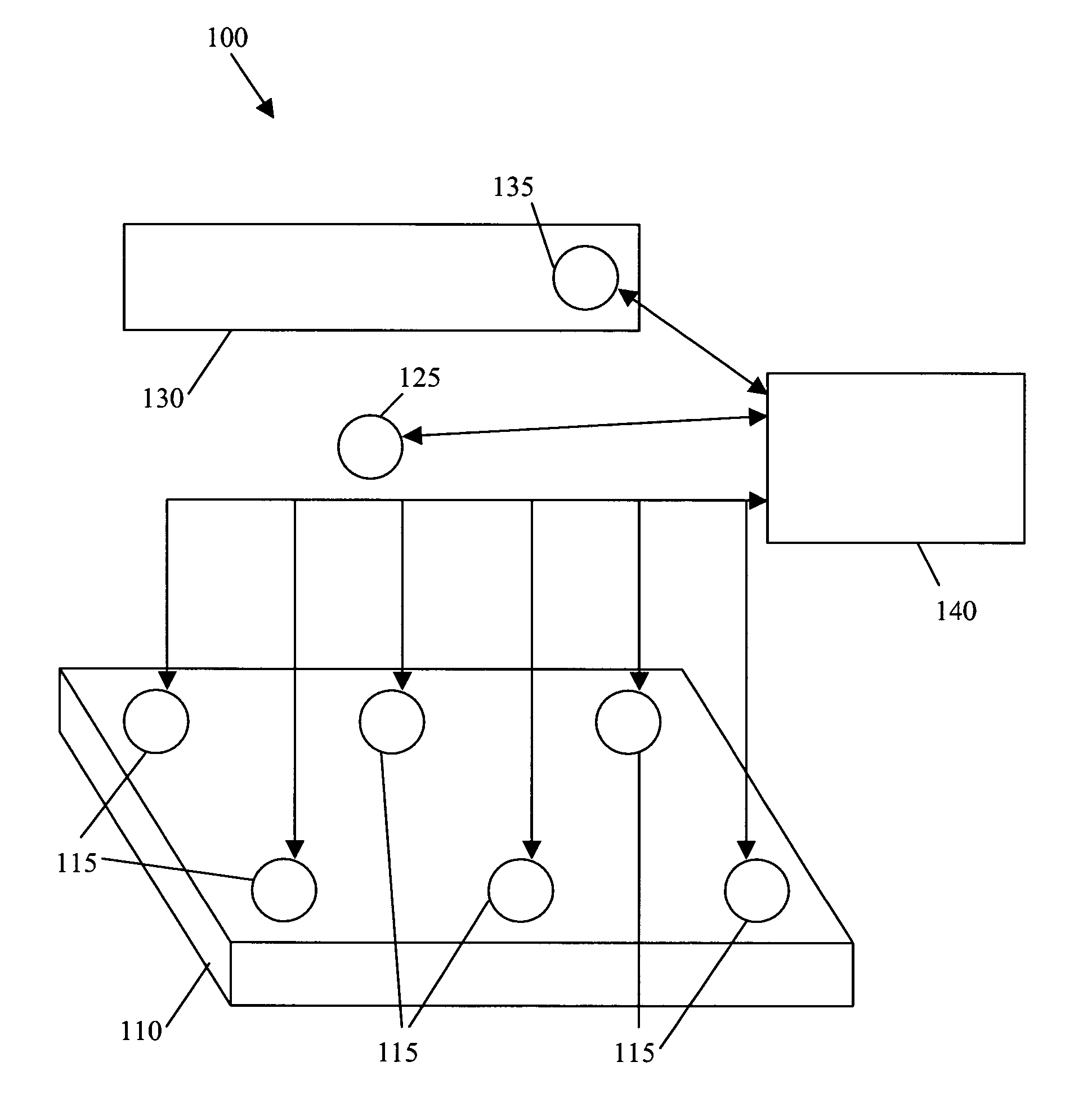
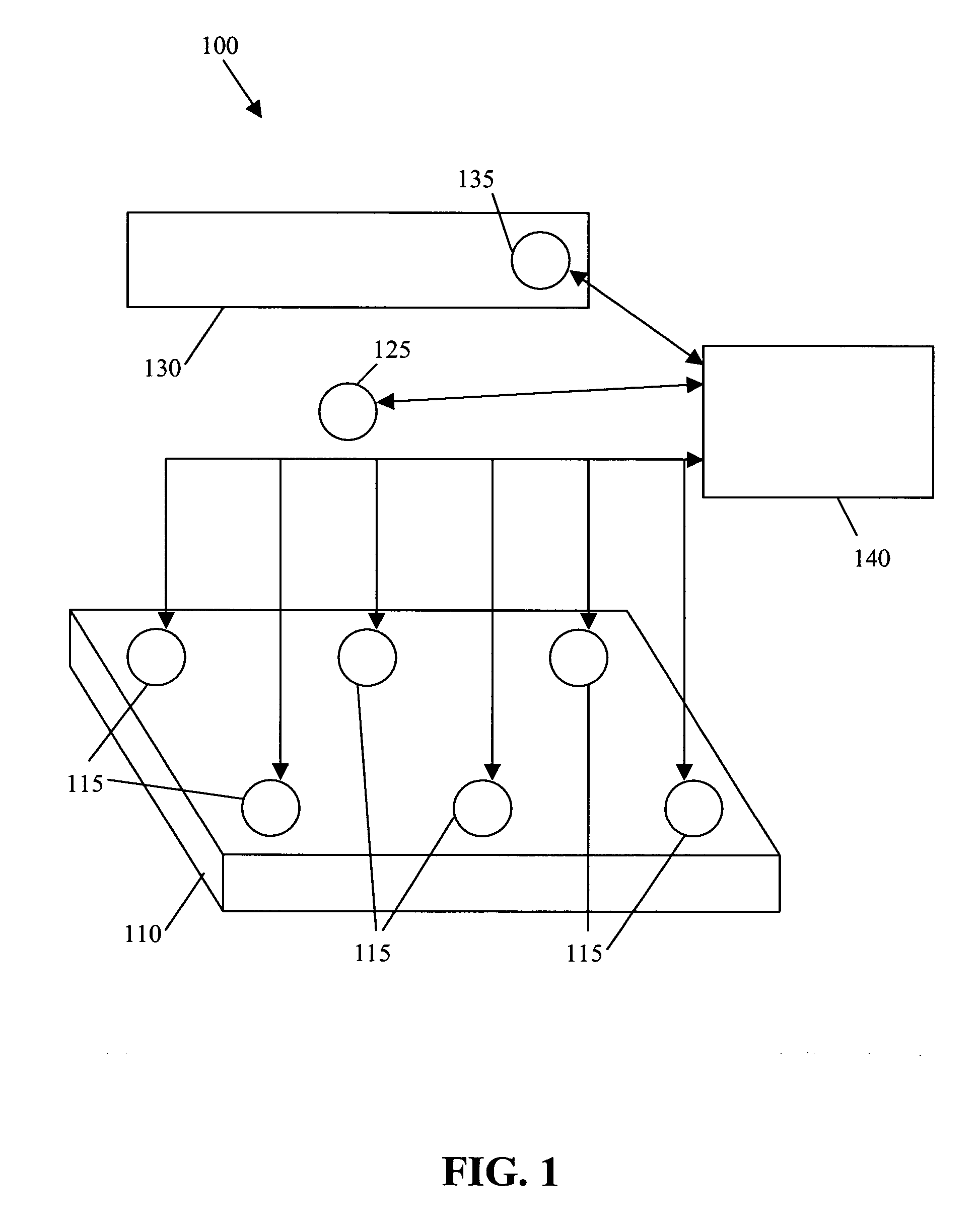
[0039]FIG. 1 illustrates an electromagnetic (“EM”) tracking system 100 used in accordance with an embodiment of the presently described technology. Tracking system 100 is configured to employ two or more coil architectures simultaneously. For example, tracking system 100 can be employed to track a position and / or orientation of one or more Industry Standard Coil Architecture (“ISCA”) electromagnetic (“EM”) trackers and a position and / or orientation of one or more single EM coils at the same time.

[0040] System 100 includes an array of single-coil receivers 115, an ISCA transmitt...


PUM


Abstract

The presently described technology provides a method for simultaneously employing two or more coil architectures in an electromagnetic tracking system. The method includes providing a transmitter that includes three single-coil transmitters, one or more receivers each including three single-coil receivers, and a receiver array that includes a plurality of single-coil receivers; tracking one or more of the single-coil transmitters of the transmitter with respect to the receiver array; and simultaneously tracking one or more of the receivers with respect to the transmitter.

Description

RELATED APPLICATIONS [0001] The present application is a continuation-in-part of U.S. patent application Ser. No. 10 / 670,054 (the “'054 application”), U.S. Patent Application Publication No. US-2005-0065433-A1, entitled “System and Method for Software Configurable Electromagnetic Tracking,” which names Peter Traneus Anderson as inventor and was filed on Sep. 24, 2003. The '054 application is hereby incorporated by reference herein in its entirety.FEDERALLY SPONSORED RESEARCH OR DEVELOPMENT [0002] Not Applicable. BACKGROUND OF THE INVENTION [0003] The present invention generally relates to an electromagnetic tracking system. In particular, the present invention relates to a system and method for the use of multiple coil architectures simultaneously in one electromagnetic (“EM”) tracking system. [0004] Medical practitioners, such as doctors, surgeons, and other medical professionals, often rely upon technology when performing a medical procedure, such as image-guided surgery (“IGS”) o...

Claims


Application Information

Patent Timeline
Patent Type & Authority Applications(United States)
IPC IPC(8): A61B5/00A61B5/06A61B19/00
CPCA61B5/06A61B19/52A61B19/5244A61B2019/502A61B2019/5251A61B5/062A61B34/20A61B90/36A61B2034/102A61B2034/2051
Inventor ANDERSON, PETER TRANEUS
Owner GENERAL ELECTRIC CO
Learn More