
Flat panel display and method of fabricating the same

a technology of flat panel display and fabrication method, which is applied in the field of flat panel display, can solve the problems of relatively weak adhesive strength of b>10/b>, polyimide used for the material of the upper and lower alignment films, etc., and achieve the effects of improving adhesive strength, reducing manufacturing variability, and being more robus

Active Publication Date: 2006-05-18
LG DISPLAY CO LTD
View PDF36 Cites 8 Cited by
  • Summary
  • Abstract
  • Description
  • Claims
  • Application Information

AI Technical Summary

Benefits of technology

[0013] An object of the present invention to provide a flat panel display and a method of fabricating the same capable with improved adhesive strength between an upper plate and a lower plate.
[0014] Another object of the present invention is to provide a flat panel display that is more robust and more tolerant of manufacturing variations.
[0015] Another object of the present invention is to provide a flat panel display that can be easily manufactured with a high yield.
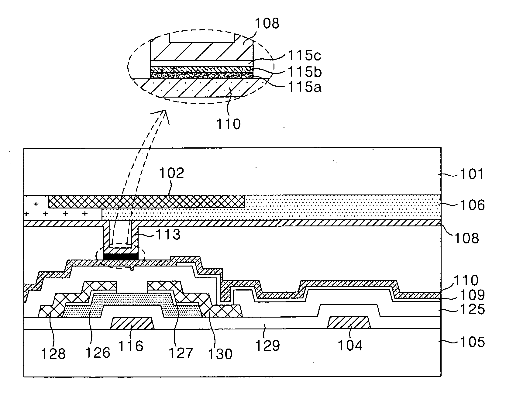
[0017] To achieve these and other advantages and in accordance with the purpose of the present invention, as embodied and broadly described, a flat panel display comprises a first plate; a second plate facing the first plate; a pattern spacer formed between the first and the second plates; and an adhesion promoter disposed overlapping the pattern spacer to improve an adhesive strength of the first and the second plates.

Problems solved by technology

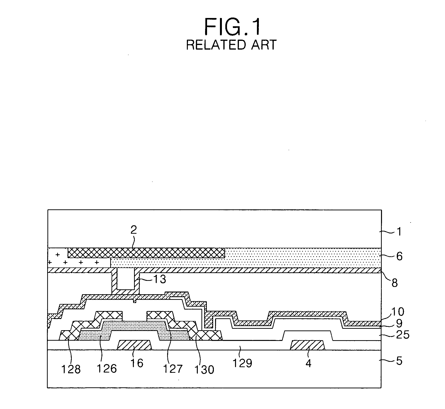
However, the polyimide used for the material of the upper and the lower alignment films 8 and 10 has a relatively weak adhesive strength.

Method used


Image

  • Flat panel display and method of fabricating the same
  • Flat panel display and method of fabricating the same
  • Flat panel display and method of fabricating the same

Examples


Embodiment Construction

[0025] Reference will now be made in detail to the preferred embodiments of the present invention, examples of which are illustrated in the accompanying drawings.

[0026] Hereinafter, the preferred embodiments of the present invention will be described in detail with reference to FIGS. 3 to 4C. FIG. 3 shows a sectional view of in-plane switching (IPS) mode liquid crystal display panel according to the present invention.

[0027] Referring to FIG. 3, the IPS mode liquid crystal display panel includes an upper plate having a black matrix 102, a color filter 106, a pattern spacer 113, an upper alignment film 108 and an adhesion promoter 115 sequentially formed on an upper substrate 101; a lower plate having a thin film transistor TFT, a common electrode 104, a pixel electrode 109, and a lower alignment film 110 formed on a lower substrate 105; and a liquid crystal material (not shown) injected into an inner space between the upper plate and the lower plate.

[0028] In the upper plate, the ...


PUM

PropertyMeasurementUnit
thicknessaaaaaaaaaa
thicknessaaaaaaaaaa
weight %aaaaaaaaaa

Abstract

A flat panel display and a method of fabricating a flat panel display is provided. The flat panel display includes a first plate, a second plate facing the first plate, a pattern spacer formed between the first and the second plates, and an adhesion promoter disposed overlapping the pattern spacer to improve an adhesive strength of the first and the second plates.

Description

[0001] This application claims the benefit of Korean Patent Application No. P2004-093701 filed in Korea on Nov. 16, 2004, which is hereby incorporated by reference. BACKGROUND OF THE INVENTION [0002] 1. Field of the Invention [0003] The present invention relates to a flat panel display, and more particularly, to a flat panel display and a method of fabricating the same with improved adhesive strength of an upper plate and a lower plate. [0004] 2. Description of the Related Art [0005] Recently, various flat panel display devices have been highlighted with reduced weight and bulk to eliminate disadvantages of cathode ray tube (CRT) technology. Such flat panel display devices include liquid crystal display (LCD) devices, field emission display (FED) devices, plasma display panel (PDP) devices, an electro-luminescence (EL) displays, etc. Among these flat panel display devices, an LCD controls the light transmittance of liquid crystal cells in accordance with video signals to display a p...

Claims


Application Information

Patent Timeline
Patent Type & Authority Applications(United States)
IPC IPC(8): C09K19/00
CPCG02F1/13394Y10T428/1059Y10T428/10G02F2202/28C09K2323/05C09K2323/00G02F1/1339
Inventor KIM, JIN WUKLEE, CHANG HEE
Owner LG DISPLAY CO LTD
Learn More