
Method and apparatus for calibrating a thermistor

a thermistor and thermistor technology, applied in the direction of positive temperature coefficient thermistors, instruments, heat measurement, etc., can solve the problems of large temperature measurement errors, excessive time and resources, and high cost of current industry methods for trimming thin film thermistors

Inactive Publication Date: 2006-05-18
PALO ALTO RES CENT INC
View PDF23 Cites 22 Cited by
  • Summary
  • Abstract
  • Description
  • Claims
  • Application Information

AI Technical Summary

Benefits of technology

[0012] In accordance with another aspect of the present exemplary embodiments the method further comprises trimming the thermistor based on the operating temperature resistance.
[0013] In accordance with another aspect of the present exemplary embodiments, the method comprises first measuring a first resistance of the thermistor at a

Problems solved by technology

This can result in large temperature measurement errors.
These approaches, though, result in excessive cost in terms of time and resources.
The current industry method of trimming thin film thermistors is expensive.

Method used


Image

  • Method and apparatus for calibrating a thermistor
  • Method and apparatus for calibrating a thermistor
  • Method and apparatus for calibrating a thermistor

Examples


Embodiment Construction

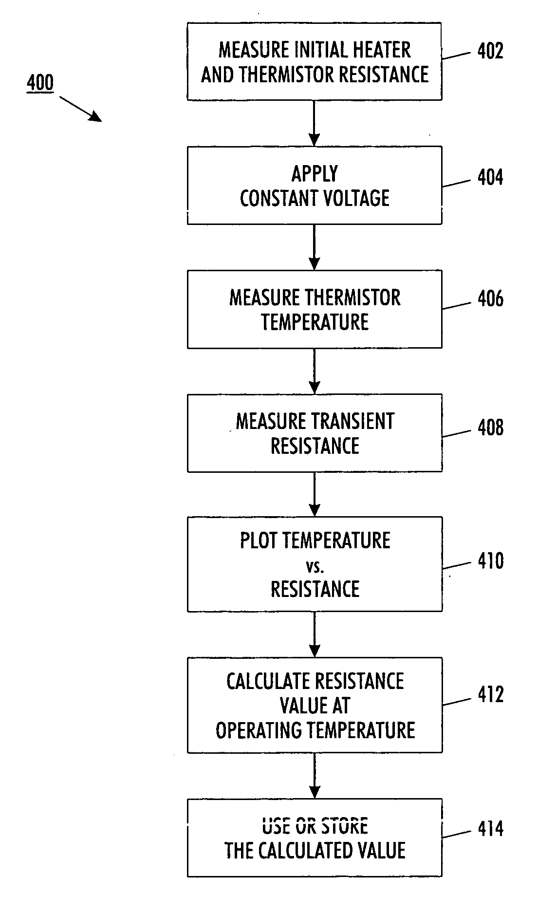
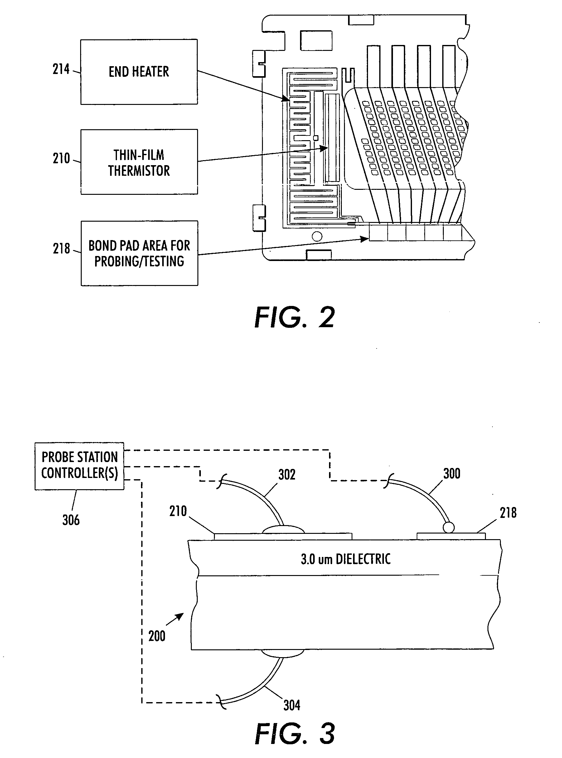
[0028] The presently described embodiments are directed to a calibration method and system for thin film thermistors that are locally heated with integrated thin film heaters. This presently described technique(s) results in high heating efficiency. Initially, print head temperature is either measured or referenced. Then, transient thermistor resistances are measured and used to determine the thermistor resistance at a higher temperature. Notably, this calibration method is advantageously implemented as a step of an existing process without having to expose the print heads to operating temperatures. Thus, calibration according to these presently described embodiments will be virtually transparent to the process, with virtually no added costs of time or resources.

[0029] In some implementations of the presently described embodiments, trimming of the thermistors may be required once calibrated. Trimming thermistors typically requires changing the fabricated resistance to a set resista...


PUM

PropertyMeasurementUnit
Temperatureaaaaaaaaaa
Poweraaaaaaaaaa
Electrical resistanceaaaaaaaaaa

Abstract

The presently described embodiments are directed to a calibration method and system for thin film thermistors that are locally heated with integrated thin film heaters. Initially, print head temperature is either measured or referenced. Then, transient thermistor resistances are measured and used to determine the thermistor resistance at a higher temperature. Notably, this calibration method is advantageously implemented as a step of an existing process without having to expose the print heads to operating temperatures. In some implementations of the presently described embodiments, trimming of the thermistors may be required once calibrated.

Description

BACKGROUND [0001] The present exemplary embodiment relates to a method and apparatus for calibrating a thermistor. It finds particular application in conjunction with thermistors used in liquid drop ejectors such as print heads operative to emit phase change ink, and will be described with particular reference thereto. However, it is to be appreciated that the present exemplary embodiments are also amenable to other like applications. [0002] By way of background, thermistors are often used on print heads to control temperature. In an effort to reduce cost and improve temperature control response, thermistors are deposited and patterned on a print head using thin-film or thick-film processes. Such a configuration is disclosed in co-pending and commonly assigned U.S. application Ser. No. ______, filed ______, entitled “Thin Film and Thick Film Heater and Control Architecture for a Liquid Drop Ejector” and having Michael Young et al. named as inventors (Applicant Docket No. 20031641-US...

Claims


Application Information

Patent Timeline
IPC IPC(8): G01K7/00G01K15/00G01K19/00
CPCG01K7/223Y10T29/49085G01K15/00
Inventor HO LIMB, SCOTT JONGYOUNG, MICHAEL YU TAKLITTAU, KARL A.
Owner PALO ALTO RES CENT INC
Learn More