
Multiplexed computer peripheral connection switching interface

a technology of switching interface and peripheral connection, applied in the field of computer peripheral technology, can solve the problems of increasing the number of pins and hardware complexity of the kvm device, affecting the operation of the logic chip, and being quite expensive to purchase, so as to achieve the effect of convenient implementation and cost-effectiveness

Inactive Publication Date: 2006-05-18
INVENTEC CORP
View PDF4 Cites 33 Cited by
  • Summary
  • Abstract
  • Description
  • Claims
  • Application Information

AI Technical Summary

Benefits of technology

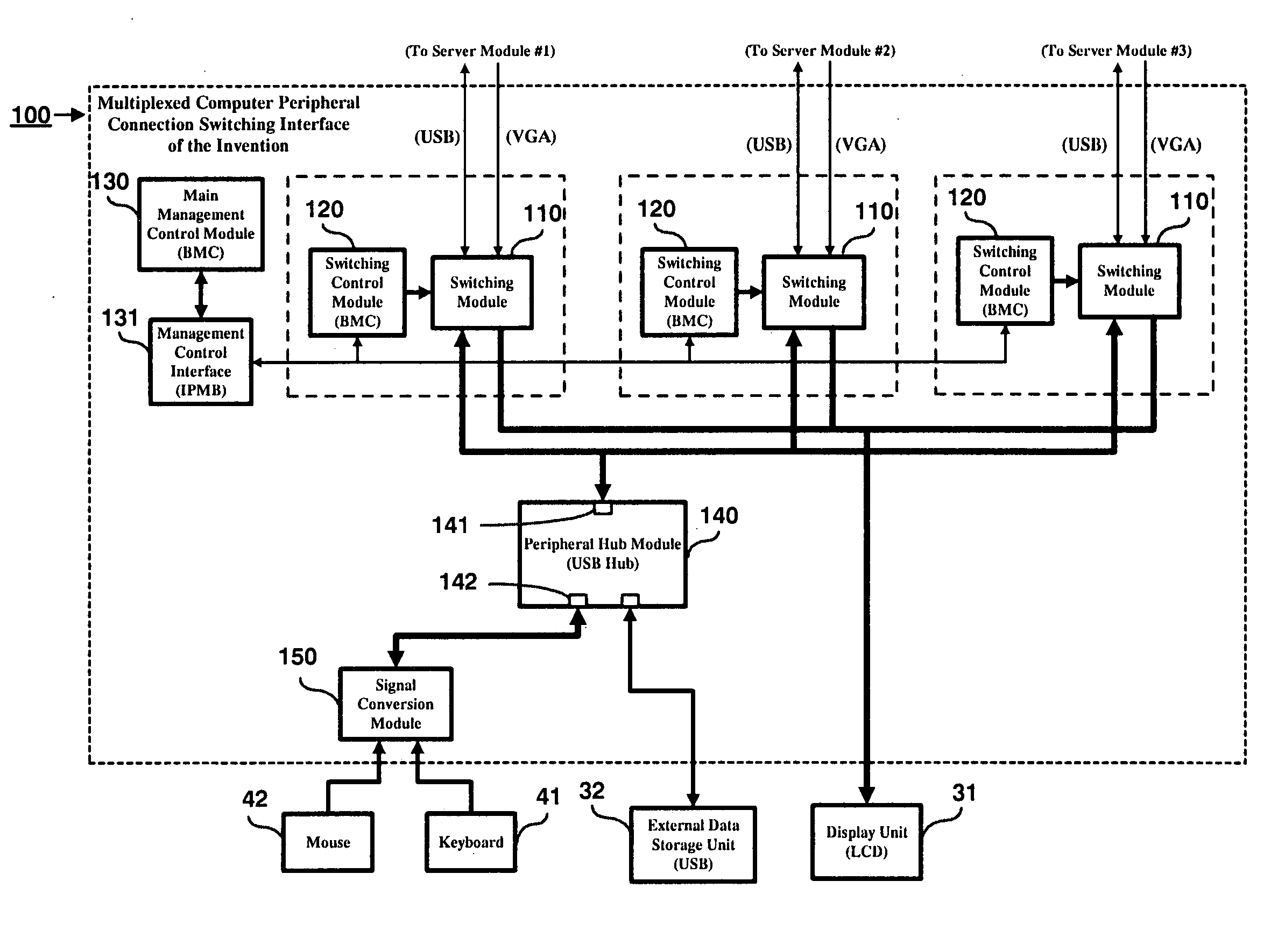
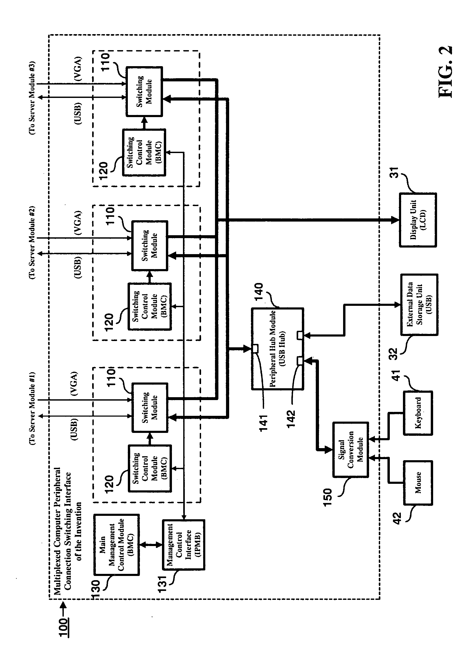
The invention is a multiplexed computer peripheral connection switching interface that allows multiple server modules in a blade server to share a group of peripheral devices without using a costly KVM switch or additional control signal circuitry. This interface uses the existing BMC management control module to link any one of the peripheral devices to any one of the server modules, making it more cost-effective and convenient than prior art. The technical effects of this invention are improved cost-effectiveness and convenience for multiple server modules in a blade server to share a group of peripheral devices.

Problems solved by technology

In such applications, since peripheral input devices are required only in the setup stage and are unnecessary during the server operation, keyboard and mouse are typically removed to save equipment cost and room space.
For this sake, blade servers are typically unequipped with keyboard and mouse during actual operation, and keyboard and mouse are externally coupled to blade servers only when it is necessary to perform system management tasks.
One drawback to the use of KVM device for USB / VGA switching, however, is that it requires additional control signal circuitry to be added to the KVM device, which would considerably increase the number of pins and hardware complexity on the KVM device, and therefore is quite costly and laborious to implement.
One drawback to this solution, however, is that this kind of logic chip is quite costly to purchase and also requires the addition of extra control signal circuitry, and therefore is nonetheless quite costly and laborious to implement.

Method used


Image

  • Multiplexed computer peripheral connection switching interface
  • Multiplexed computer peripheral connection switching interface
  • Multiplexed computer peripheral connection switching interface

Examples


Embodiment Construction

[0017] The multiplexed computer peripheral connection switching interface according to the invention is disclosed in full details by way of preferred embodiments in the following with reference to the accompanying drawings.

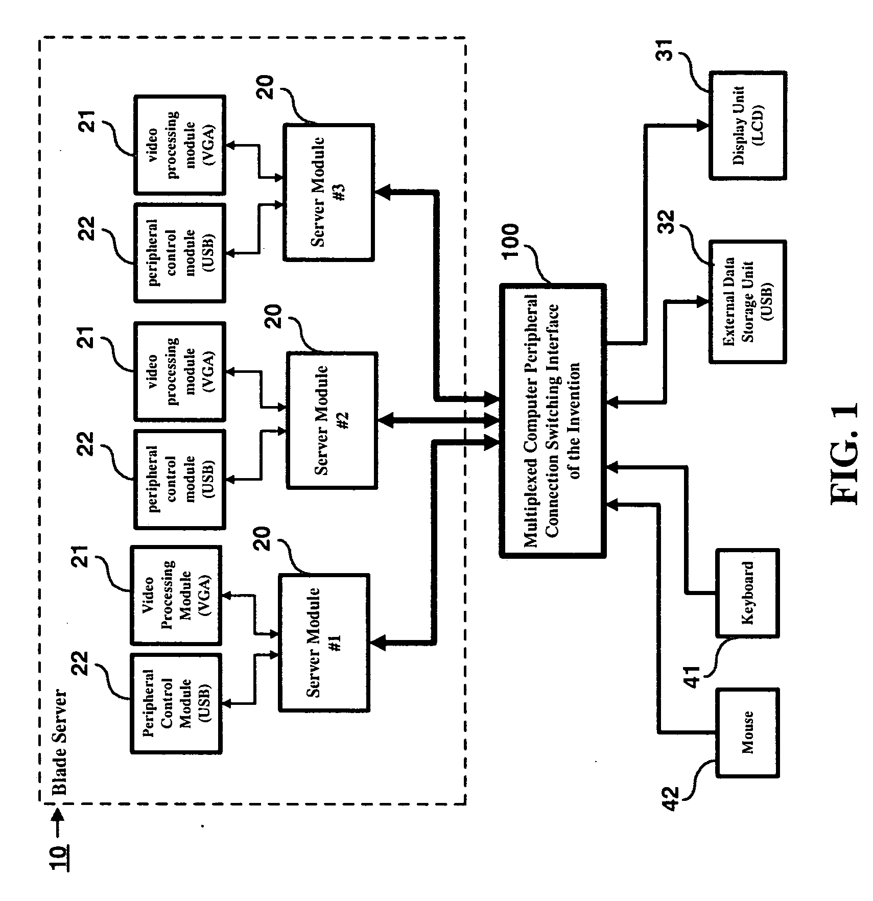
[0018]FIG. 1 is a schematic diagram showing the application architecture of the multiplexed computer peripheral connection switching interface according to the invention 100. As shown, in practical application, the multiplexed computer peripheral connection switching interface of the invention 100 is coupled to a clustered computer system (such as a blade server 10) that is equipped with a number of independent data processing units (such as a number of server modules 20 in the blade server 10), with each server module 20 being equipped with a video processing module 21 and a peripheral control module 22 where each video processing module 21 is for example a VGA (Video Graphics Array) module while each peripheral control module 22 is for example a USB (Universal ...


PUM


Abstract

A multiplexed computer peripheral connection switching interface is proposed, which is designed for use in conjunction with a clustered computer system that is equipped with a number of independent data processing units, such as a blade server with multiple server modules, for the multiple server modules in the blade server to share an external set of peripheral devices; and which is characterized by the use of the existing BMC (Baseboard Management Controller) management control module for control of the linking between a user-specified server module and a selected one of the peripheral devices. This feature allows multiple server modules in a blade server to share a group of peripheral devices in a more cost-effective and convenient way than prior art.

Description

BACKGROUND OF THE INVENTION [0001] 1. Field of the Invention [0002] This invention relates to computer peripheral technology, and more particularly, to a multiplexed computer peripheral connection switching interface which is designed for use in conjunction with a clustered computer system that is equipped with a number of independent data processing units, such as a blade server with multiple server modules, for the multiple server modules in the blade server to share a group of peripheral devices, including, for example, a keyboard, a mouse, a display unit, and a data storage unit (such as a portable flash memory module). [0003] 2. Description of Related Art [0004] Blade server is a clustering type of network server that is characterized by the use of a circuit board enclosure to integrate a cluster of server modules (commonly called “blades”), with all of these server modules providing the same server functionality. In other words, a blade server can respond to a client's request...

Claims


Application Information

Patent Timeline
Patent Type & Authority Applications(United States)
IPC IPC(8): H04L12/56
CPCG06F3/0227G06F3/023
Inventor LEE, CHUN-LIANG
Owner INVENTEC CORP
Learn More