Turbidity sensor
- Summary
- Abstract
- Description
- Claims
- Application Information
AI Technical Summary
Benefits of technology
Problems solved by technology
Method used
Image
Examples
Embodiment Construction
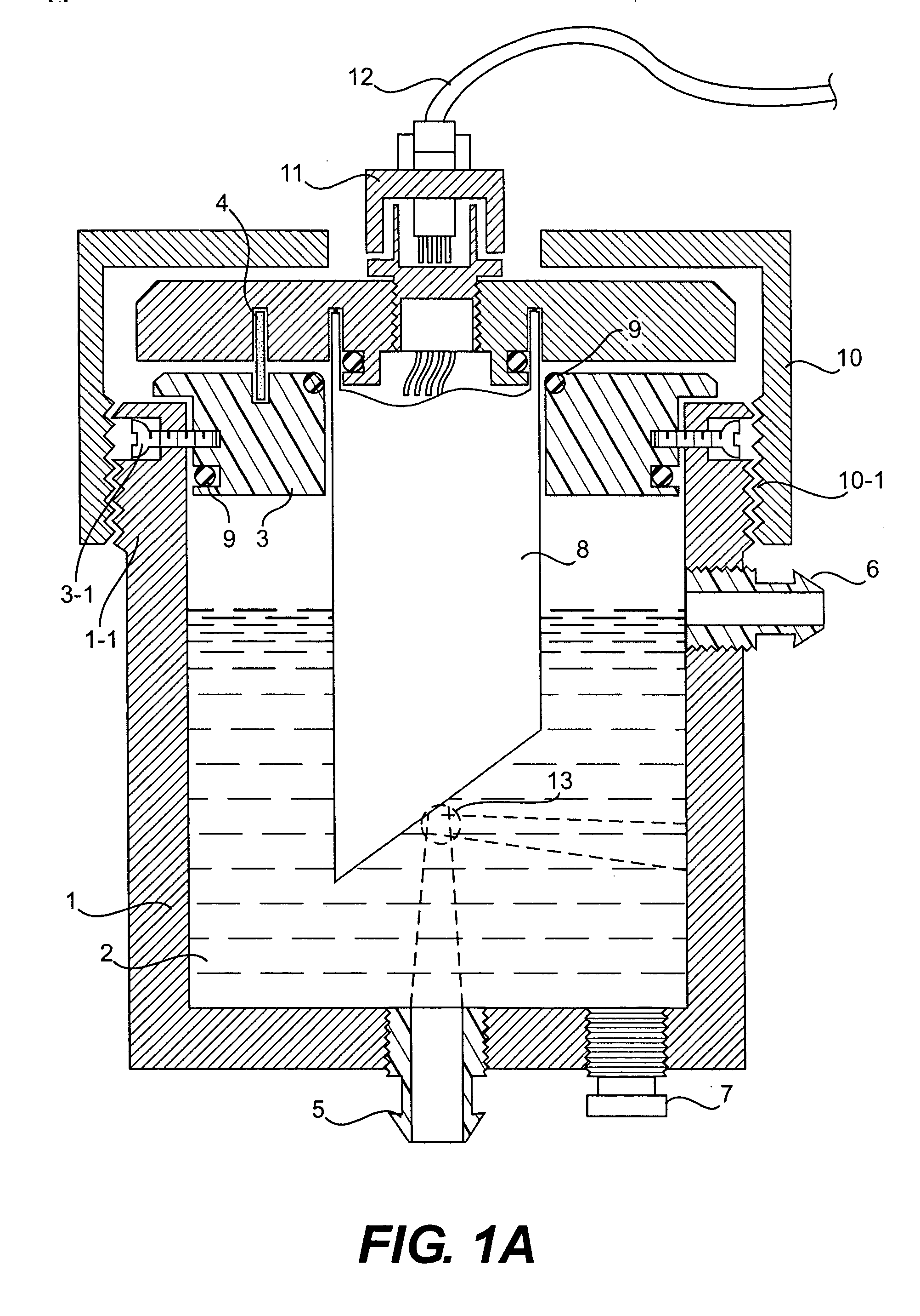
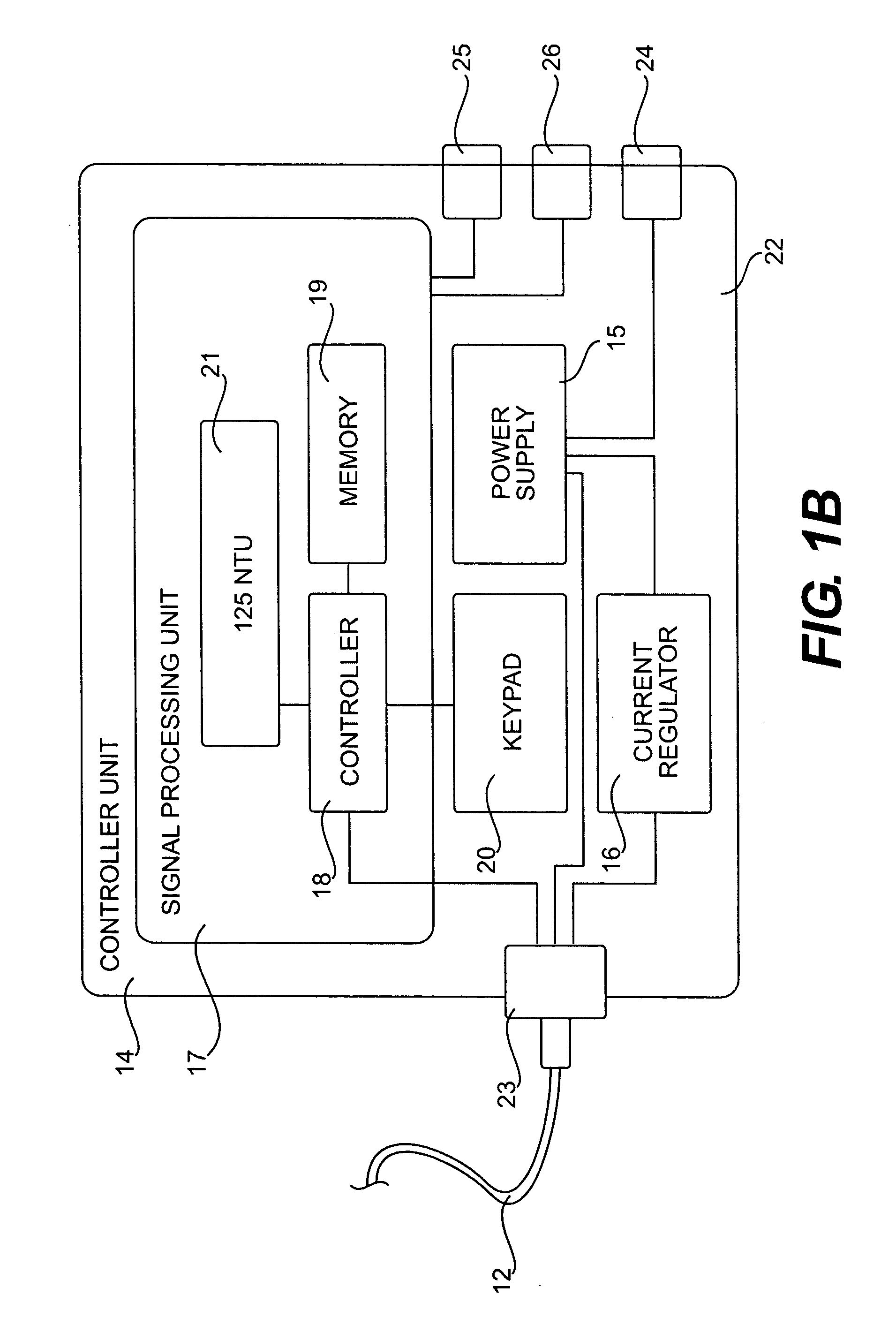
[0025] In FIG. 1A, a turbidity sensor for testing a fluid sample 2 according to the present invention includes a sample chamber 1, a sensor unit 8, and a controller unit 14. The sample chamber 1 has at the top portion a mounting ring 3 for inserting the sensor unit 8 and a positioning pin 4, at least one inlet 5, at least one outlet 6, a plug 7 for releasing the sample 2 when necessary (e.g., cleaning), a chamber cap 10 with threads 10-1 on the inner surface to be screwed with threads 1-1 on the outer surface of the chamber 1, a cable connector 11 connecting a cable 12 to the sensor unit 8. The mounting ring 3 can be secured to the chamber 1 via a pair of screws 3-1. Some O-rings 9 are provided between the chamber 1, the mounting ring 3 and the sensor unit 8 to secure and seal them against each other. The cable 12 transfers signals between the sensor unit 8 and a controller unit 14 shown in FIG. 1B. The sample chamber 1 and the chamber cap 10 are made of an opaque material, such as ...
PUM
 Abstract
Description
Claims
Application Information
 - R&D
- Intellectual Property
- Life Sciences
- Materials
- Tech Scout
- Unparalleled Data Quality
- Higher Quality Content
- 60% Fewer Hallucinations
Browse by: Latest US Patents, China's latest patents, Technical Efficacy Thesaurus, Application Domain, Technology Topic, Popular Technical Reports.
© 2025 PatSnap. All rights reserved.Legal|Privacy policy|Modern Slavery Act Transparency Statement|Sitemap|About US| Contact US: help@patsnap.com


