Liquid crystal display device

a liquid crystal display and display device technology, applied in non-linear optics, instruments, optics, etc., can solve the problem that the display of accurate color cannot be realized by a simple control, and achieve the effect of facilitating maintenance, and reducing the thickness of the liquid crystal layer

Inactive Publication Date: 2006-05-18
SANYO ELECTRIC CO LTD
View PDF4 Cites 22 Cited by
  • Summary
  • Abstract
  • Description
  • Claims
  • Application Information

AI Technical Summary

Benefits of technology

[0019] In this manner, the spacer is provided only in a region, among the plurality of pixels, in which the thickness of the liquid crystal layer should be reduced compared to the other pixels or in pixel regions corresponding to a plurality of display colors in which the thickness of the liquid crystal layer should be reduced compared to the other pixels. Therefore, all of the provided spacers contributes to defining the thickness of the liquid crystal layer and no wasteful spacer is provided. Thus, the gap can be maintained efficiently, accurately, and easily.

Problems solved by technology

However, when a characteristic of the liquid crystal has a wavelength dependency and the pixels associated with different colors have the same structure, display in accurate color cannot be realized by a simple control.

Method used


Image

  • Liquid crystal display device
  • Liquid crystal display device
  • Liquid crystal display device

Examples


Embodiment Construction

[0024] Preferred embodiments of the present invention will now be described referring to the drawings.

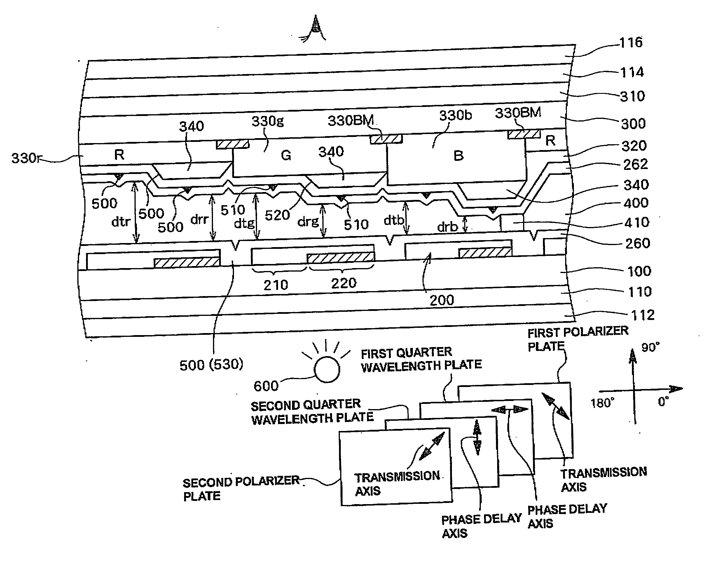
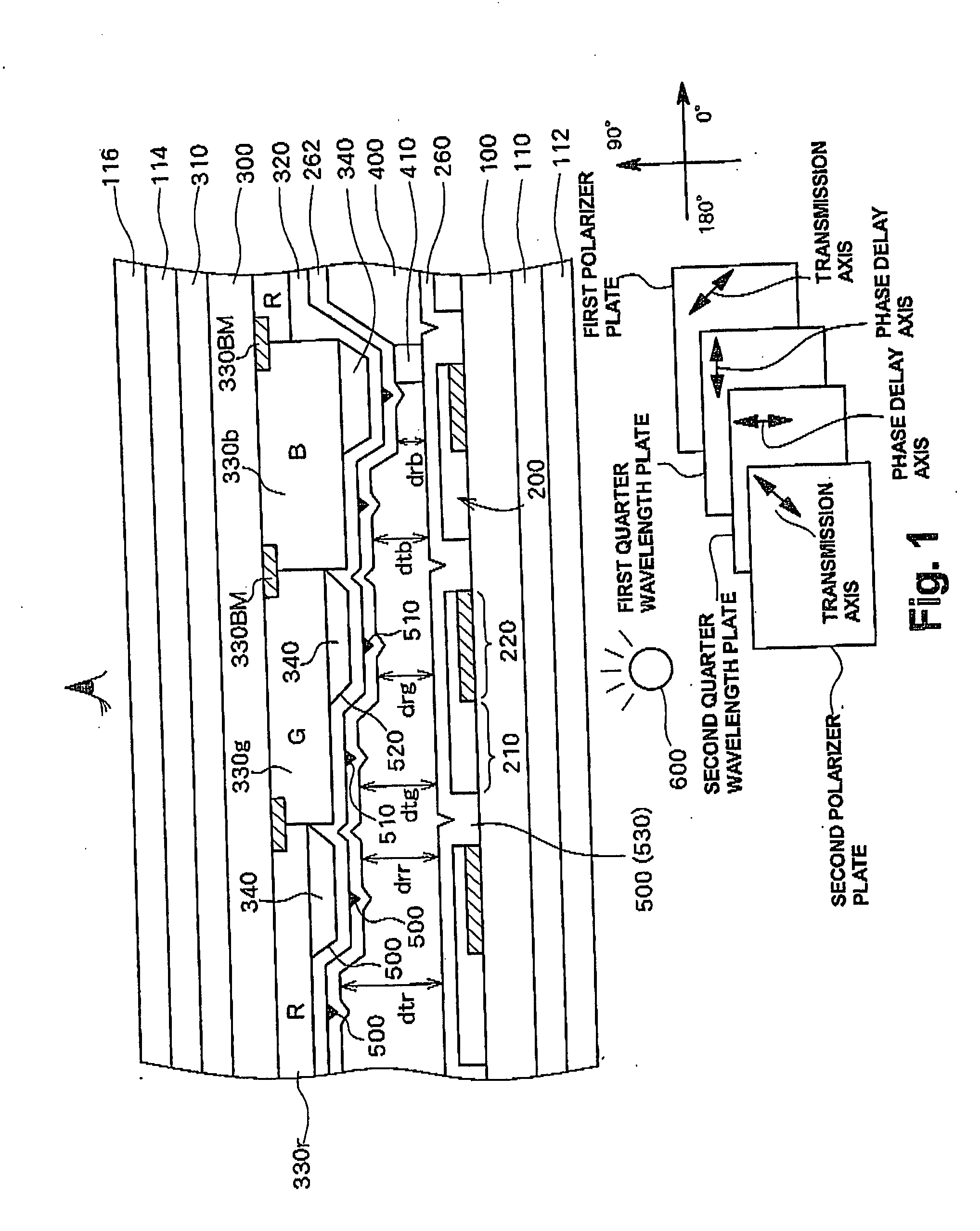
[0025]FIG. 1 schematically shows a cross sectional structure when a transflective active matrix LCD is used as an LCD according to a preferred embodiment of the present invention. The drawings including FIG. 1 show the elements schematically in order to allow understanding of the structure of the embodiment and the dimensions in the drawings differ from those of the actual device. In the transflective LCD according to the present embodiment, a first substrate 100 and a second substrate 300 on which a first electrode 200 and a second electrode 320 are formed respectively on the opposing surfaces are adhered with a predetermined gap therebetween and a liquid crystal layer 400 is sealed in the gap between the substrate. A plurality of pixels are placed in a display region in a matrix form and a transmissive region 210 and a reflective region 220 are formed in each pixel region.

[0026]...


PUM

PropertyMeasurementUnit
coloraaaaaaaaaa
thicknessaaaaaaaaaa
display colorsaaaaaaaaaa

Abstract

In a liquid crystal display device, a thickness of a liquid crystal layer in each pixel is adjusted based on a display color (red, green, and blue). For example, thicknesses of color filters corresponding to the display colors are varied based on the display color to set the thickness (cell gap) of the liquid crystal layer in each pixel to a predetermined value corresponding to a transmittance of the liquid crystal. A spacer provided to maintain the cell gap at a constant value is not provided in a region, among the plurality of display colors, having a large cell gap and the spacer is provided above the color filter or the like at a pixel region having smaller cell gap. With this structure, all spacers provided within a cell can substantially contribute to maintaining the gap.

Description

CROSS-REFERENCE TO RELATED APPLICATIONS [0001] The entire disclosure of Japanese Patent Application No. 2004-286180 including specification, claims, drawings, and abstract is incorporated herein by reference. BACKGROUND OF THE INVENTION [0002] 1. Field of the Invention [0003] The present invention relates to a liquid crystal display device and in particular to a multi-gap liquid crystal display device having regions with different thicknesses of a liquid crystal layer. [0004] 2. Description of the Related Art [0005] Because liquid crystal display devices (hereinafter simply referred to as “LCD”) have advantages such as a thin thickness and low power consumption, the LCDs are widely in use as a computer monitor and a monitor for a portable information device or the like. In the LCD, liquid crystal is sealed between a pair of substrates and display is realized by controlling, using electrodes formed on the substrates, alignment of the liquid crystal positioned between the electrodes. ...

Claims


Application Information

Patent Timeline
Patent Type & Authority Applications(United States)
IPC IPC(8): G02F1/1335
CPCG02F1/133371G02F1/133514G02F1/13394G02F1/1339
Inventor YAMADA, TSUTOMUKOMA, NORIOMAEDA, KAZUYUKI
Owner SANYO ELECTRIC CO LTD
Why Eureka
Try Eureka