
Ion source with substantially planar design

a planar design and ion source technology, applied in the direction of ion beam tubes, electric discharge lamps, instruments, etc., can solve the problems of adversely affecting the electric field potential between, adversely affecting the operability and/or efficiency of the ion source, etc., to achieve less undesirable build-up and source run more efficiently

Inactive Publication Date: 2006-05-18
GUARDIAN GLASS LLC
View PDF22 Cites 19 Cited by
  • Summary
  • Abstract
  • Description
  • Claims
  • Application Information

AI Technical Summary

Benefits of technology

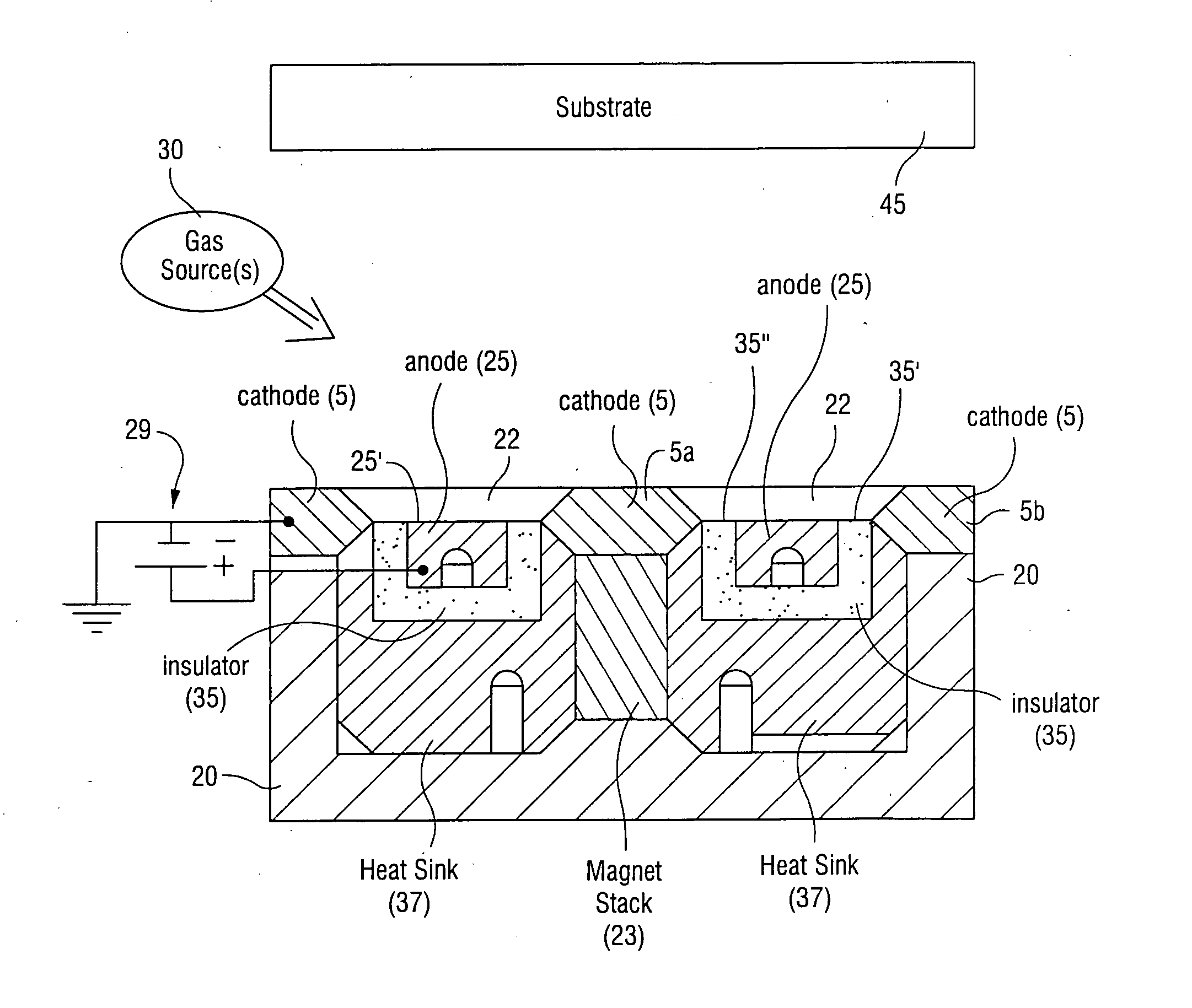
[0013] In certain example embodiments of this invention, there is provided an ion source including an anode and a cathode. In certain example embodiments, the cathode does not substantially overhang over the anode, or vice versa. Since no, or fewer, areas of overhang are provided between the anode and cathode, there is less undesirable build-up on the anode and / or cathode during operation of the ion source so that the source can run more efficiently. Moreover, in certain example embodiments, an insulator such as a ceramic or the like is provided between the anode and cathode.
[0014] In certain example embodiments of this invention this substantially planar design, where there is no area of overhang between the anode / cathode on the side of the ion source facing the substrate, is advantageous in that: (a) it permits high current operation at low potential thereby yielding a high flux of potentially low energy ions toward the substrate; (b) the lack or reduction of overhang areas or interior spaces between the anode / cathode reducing the amount of undesirable build-ups on the anode and / or cathode during source operation and thus reduces the required frequency of cleaning and / or duty cycle of the source; and / or (c) it creates an ion source which optimizes the effectiveness of a magnetron mode of cleaning.

Problems solved by technology

Unfortunately, certain of the elements in acetylene and / or silane gas is / are insulative in nature (e.g., carbide may be an insulator in certain applications).
This can interfere with gas flow through the gap and / or aperture 15, and / or it can reduce net current thereby adversely affecting the electric field potential between the anode and cathode proximate slit / aperture 15.
Such deposits resistively limit the amount of current that can flow through the source; this adversely interferes with the operability and / or efficiency of the ion source especially over significant lengths of time.
This unfortunately can also result in micro-particles from the deposits making their way into a film being deposited on the substrate.
In either case, operability and / or efficiency of the ion beam source is adversely affected.

Method used


Image

  • Ion source with substantially planar design
  • Ion source with substantially planar design
  • Ion source with substantially planar design

Examples


Embodiment Construction

[0013] In certain example embodiments of this invention, there is provided an ion source including an anode and a cathode. In certain example embodiments, the cathode does not substantially overhang over the anode, or vice versa. Since no, or fewer, areas of overhang are provided between the anode and cathode, there is less undesirable build-up on the anode and / or cathode during operation of the ion source so that the source can run more efficiently. Moreover, in certain example embodiments, an insulator such as a ceramic or the like is provided between the anode and cathode.

[0014] In certain example embodiments of this invention this substantially planar design, where there is no area of overhang between the anode / cathode on the side of the ion source facing the substrate, is advantageous in that: (a) it permits high current operation at low potential thereby yielding a high flux of potentially low energy ions toward the substrate; (b) the lack or reduction of overhang areas or in...


PUM


Abstract

In certain example embodiments of this invention, there is provide an ion source including an anode and a cathode. In certain example embodiments, the cathode does not overhang over the anode, or vice versa. Since no, or fewer, areas of overhang are provided between the anode and cathode, there is less undesirable build-up on the anode and / or cathode during operation of the ion source so that the source can run more efficiently. Moreover, in certain example embodiments, an insulator such as a ceramic or the like is provided between the anode and cathode.

Description

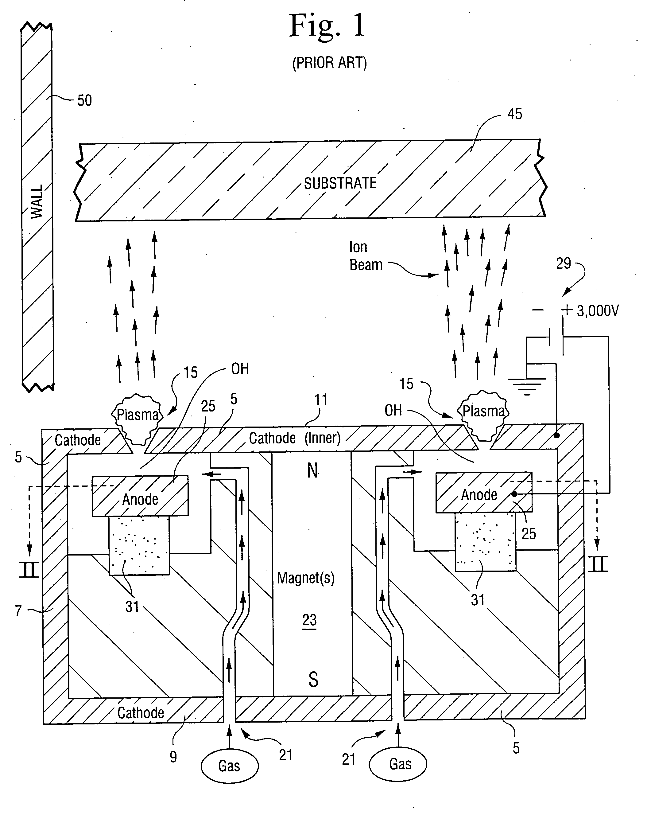
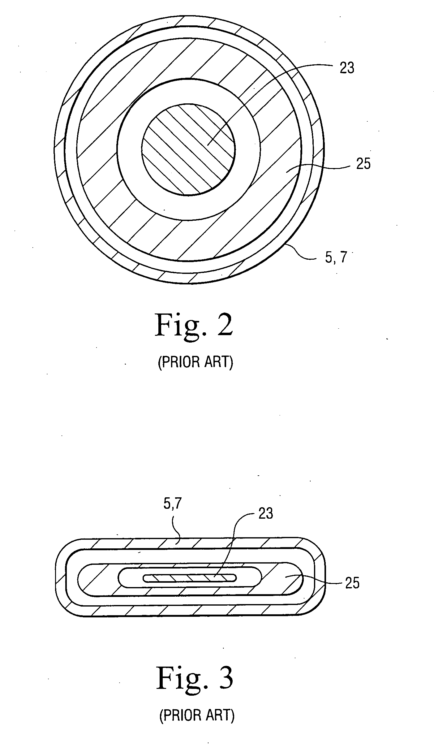
[0001] This invention relates to an ion source having an improved design which aids in cleaning and / or operation. In certain example embodiments, the ion source comprises a substantially planar design so that there is no or substantially no area where the cathode overhangs the anode. BACKGROUND OF THE INVENTION [0002] An ion source is a device that causes gas molecules to be ionized and then accelerates and emits the ionized gas molecules and / or atoms toward a substrate. Such an ion source may be used for various purposes, including but not limited to cleaning a substrate, surface activation, polishing, etching, and / or deposition of thin film coatings / layer(s). Example ion sources are disclosed, for example, in U.S. Pat. Nos. 6,359,388; 6,037,717; 6,002,208; and 5,656,819, the disclosures of which are all hereby incorporated herein by reference. [0003]FIGS. 1-2 illustrate a conventional Hall-effect, anode layer ion source. In particular, FIG. 1 is a side cross-sectional view of an i...

Claims


Application Information

Patent Timeline
Patent Type & Authority Applications(United States)
IPC IPC(8): H01J7/24
CPCH01J3/04H01J27/143H01J37/08
Inventor LUTEN, HENRY A.VEERASAMY, VIJAYEN S.
Owner GUARDIAN GLASS LLC
Learn More