
Fuel tank system having enhanced durability and reduced permeation

Inactive Publication Date: 2006-05-18
PLASTIC OMNIUM ADVANCED INNOVATION & RES SA
View PDF19 Cites 46 Cited by
  • Summary
  • Abstract
  • Description
  • Claims
  • Application Information

AI Technical Summary

Benefits of technology

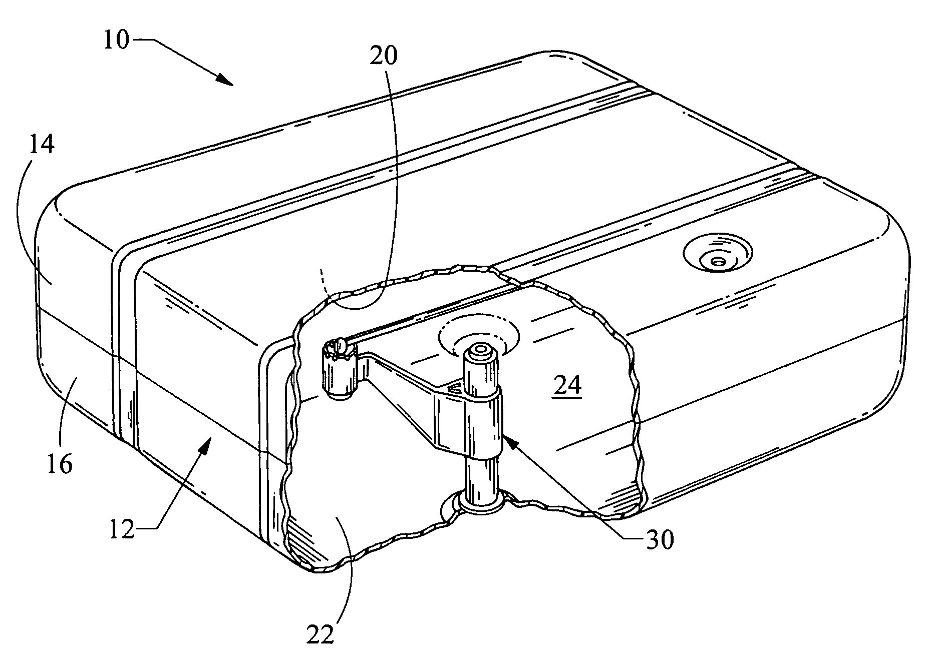
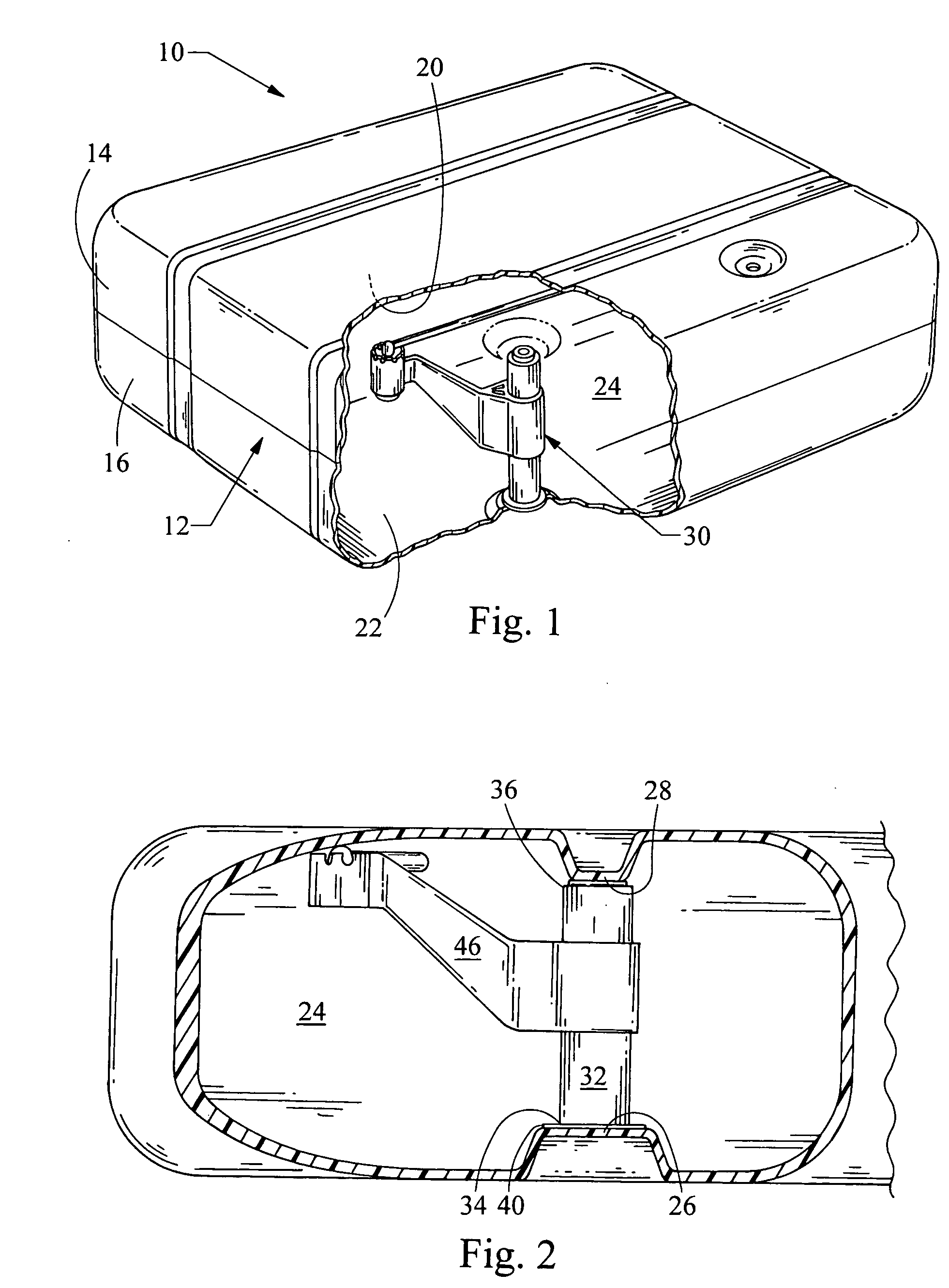
[0004] The present invention provides a fluid tank system having enhanced durability and reduced permeation features. The system comprises a fuel tank including an internalized fuel system components, e.g., and a mounting apparatus. The mounting apparatus provides added support to the fuel tank and positively positions components therein for limited movement in the fuel tank.
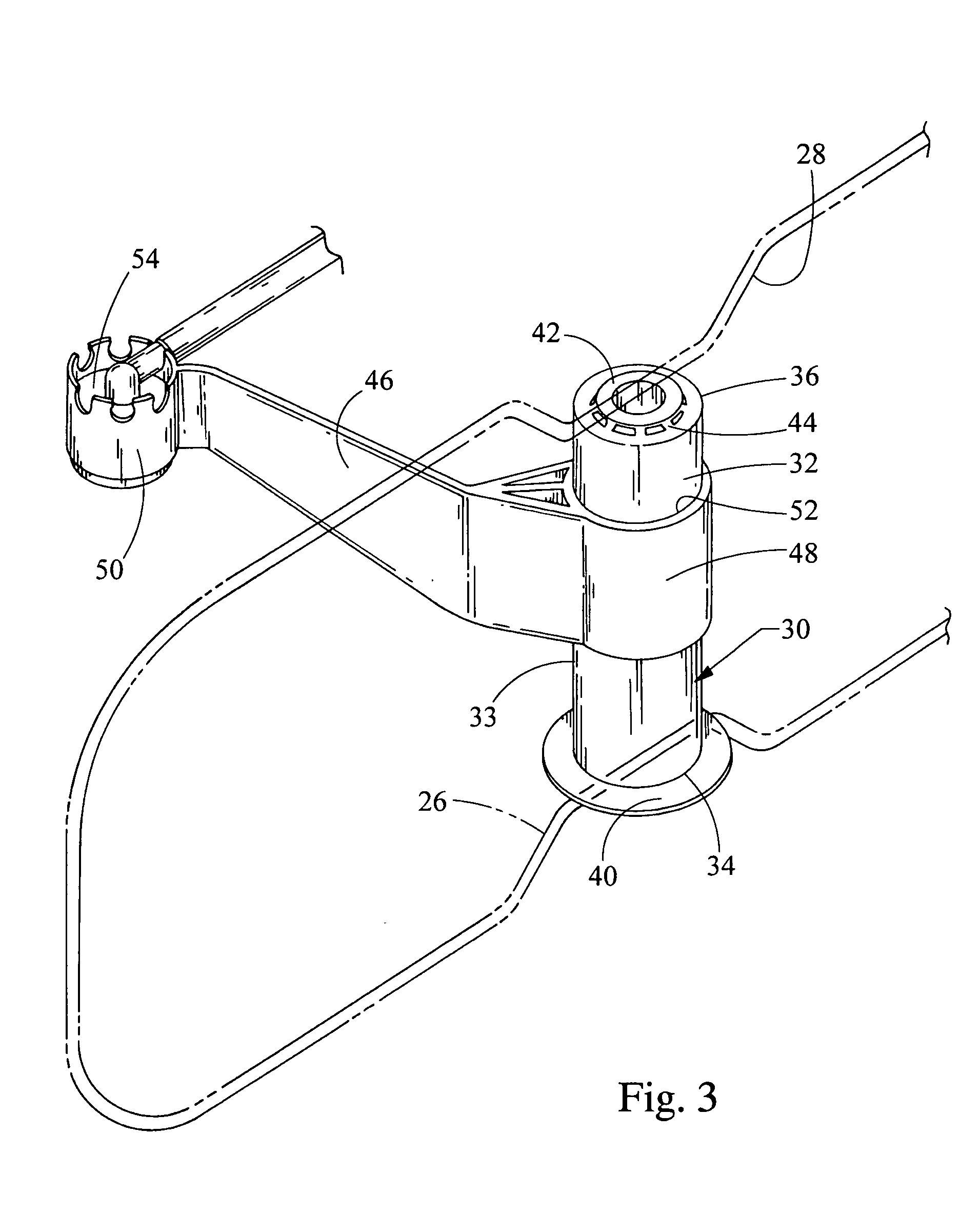
[0005] In one embodiment, the present invention provides a fluid tank system having enhanced durability and reduced permeation. The fluid tank system comprises a fuel tank having first and second outer portions. The system further comprises a support portion having a body and first and second ends. The first end has a flange configured to engage the first outer portion of the fuel tank for providing support to the system. The second end has a reduced cross-sectional portion configured to engage the second outer portion of the fuel tank for limited movement from pressure and vacuum forces. The system further comprises a valve retainer arm having an attachment end attached to the support portion. The attachment end extends to a valve retainer end for retaining the internalized fuel system components within the fuel tank.

Problems solved by technology

A problem in plastic tanks that manufacturers have experienced is that fuel may permeate through the walls of the plastic tank.
One solution to this problem has been to internalize components in the fuel tank due to the potential likelihood of leakage of fuel vapors through the components.
However, manufacturers have been challenged in internalizing such components while maintaining support to the fuel tank and limiting movement of the internalized components in the fuel tank.
Manufacturers have also been challenged in providing support within the fuel tank in view of pressure and vacuum forces therein.
Additionally, manufacturers are further challenged in positioning the internalized components within fuel tanks.

Method used


Image

  • Fuel tank system having enhanced durability and reduced permeation
  • Fuel tank system having enhanced durability and reduced permeation
  • Fuel tank system having enhanced durability and reduced permeation

Examples


Embodiment Construction

[0018] The present invention generally provides enhanced support to a fluid tank system and localized positive positioning of internalized components within the fluid tank system. Embodiments of the present invention provide enhanced support to a fuel tank of the system by incorporating a mounting assembly that is configured to be disposed between inner walls of the fuel tank. The mounting assembly provides added support to the fuel tank and to internalized fuel tank components, such as internal vapor valves, by attaching to opposing inner walls of the fuel tank. Moreover, the placement of the mounting assembly within the fuel tank provides enhanced accuracy or positive placement for internalized components within the fuel tank. Furthermore, the mounting assembly includes a safety feature that minimizes damage to the system at threshold pressure and low vacuum conditions within the fuel tank.

[0019]FIG. 1 illustrates a fluid tank system 10 having enhanced durability and reduced perm...


PUM


Abstract

A mounting apparatus for an internalized fuel system of a fuel tank. The apparatus comprises a support portion and a valve retainer arm attached about the support portion. The support portion has a body and first and second ends. The first end has a connecting flange configured to engage the fuel tank and the second end has a reduced cross-sectional portion attached thereto to provide flexibility to the fuel tank from pressure and vacuum forces. The valve retainer arm has an attachment end attached about the support portion. The attachment end extends to a valve retainer end for retaining the internalized fuel system within the fuel tank.

Description

BACKGROUND OF THE INVENTION [0001] The present invention relates to fuel tank systems having enhanced durability and reduced permeation. [0002] Fluid tanks are common in several industries. For example, fuel tanks for motorized vehicles have been used for many years. Many of the current fuel tanks installed in motorized vehicles are made of plastic or metal. Plastic storage containers provide a number of advantages over those made of other materials. Some advantages include reduced weight, reduced cost for both materials and construction, and greater flexibility and shape. Along with these advantages, the ability of certain plastic containers to stretch or flex makes them useful in automotive applications. A problem in plastic tanks that manufacturers have experienced is that fuel may permeate through the walls of the plastic tank. [0003] Several approaches have been taken to reduce permeation through the fuel tanks and increase support or stability of the fuel tank systems. One sol...

Claims


Application Information

Patent Timeline
IPC IPC(8): B62D33/00
CPCB60K15/03177B60K15/073B60K2015/03059B60K2015/03453
Inventor POTTER, JAMES F.BORGHI, CORY
Owner PLASTIC OMNIUM ADVANCED INNOVATION & RES SA
Learn More