
Endoscope

Active Publication Date: 2017-04-20
FUJIFILM CORP
View PDF4 Cites 5 Cited by
  • Summary
  • Abstract
  • Description
  • Claims
  • Application Information

AI Technical Summary

Benefits of technology

The invention aims to make the endoscope's insertion portion smaller and stronger. This is achieved by using a flexible circuit board instead of a rigid circuit board, which reduces the risk of damage to the circuit board and allows for a smaller diameter endoscope.

Problems solved by technology

When the distance between the land and the bent portion is reduced, there is a fear that the land of the flexible circuit board may be separated from a corresponding terminal of the image sensor as soon as the circuit board is bent.
Thus, there is a fear that the flexible circuit board may be broken.

Method used


Image

  • Endoscope
  • Endoscope
  • Endoscope

Examples


Embodiment Construction

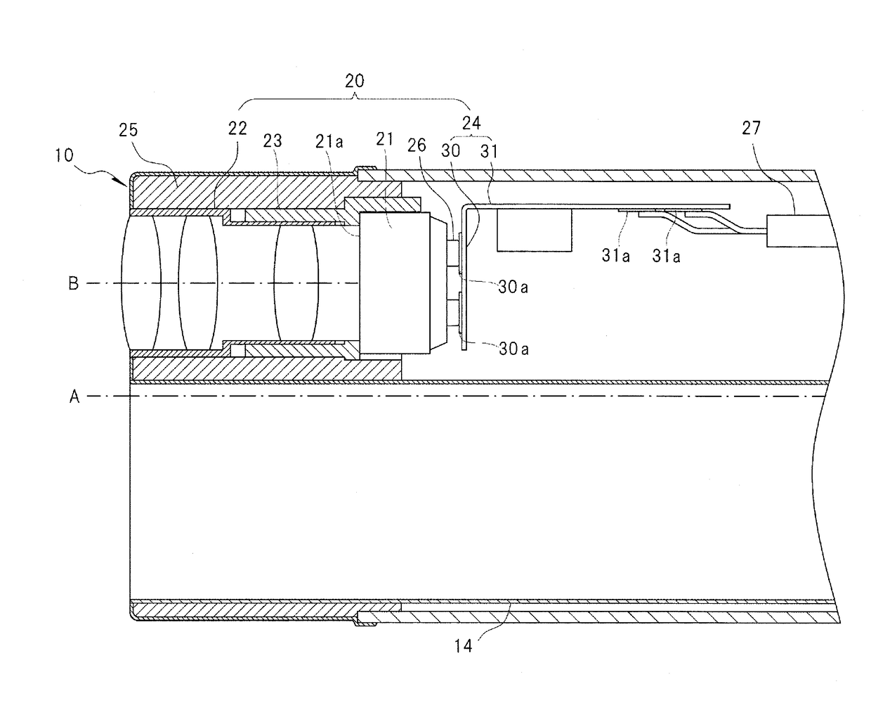
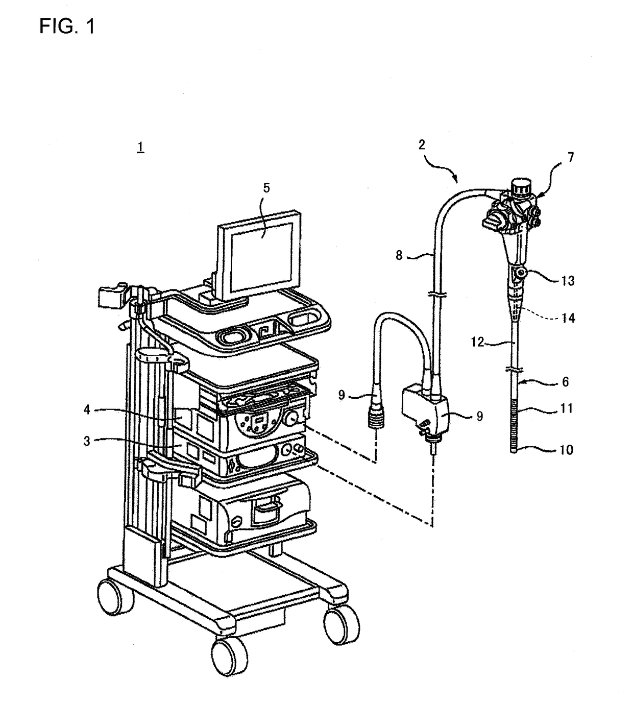
[0049]FIG. 1 shows an example of an endoscope system for explaining an embodiment of the invention.

[0050]An endoscope system 1 has an endoscope 2, a light source unit 3, and a processor unit 4. The endoscope 2 has an insertion portion 6, an operation portion 7, and a universal cord 8. The insertion portion 6 is inserted into a subject to be inspected. The operation portion 7 is connected to the insertion portion 6. The universal cord 8 extends from the operation portion 7. The insertion portion 6 is constituted by a front end portion 10, a bent portion 11, and a soft portion 12. The bent portion 11 is connected to the front end portion 10. The bent portion 11 and the operation portion 7 are connected through the soft portion 12.

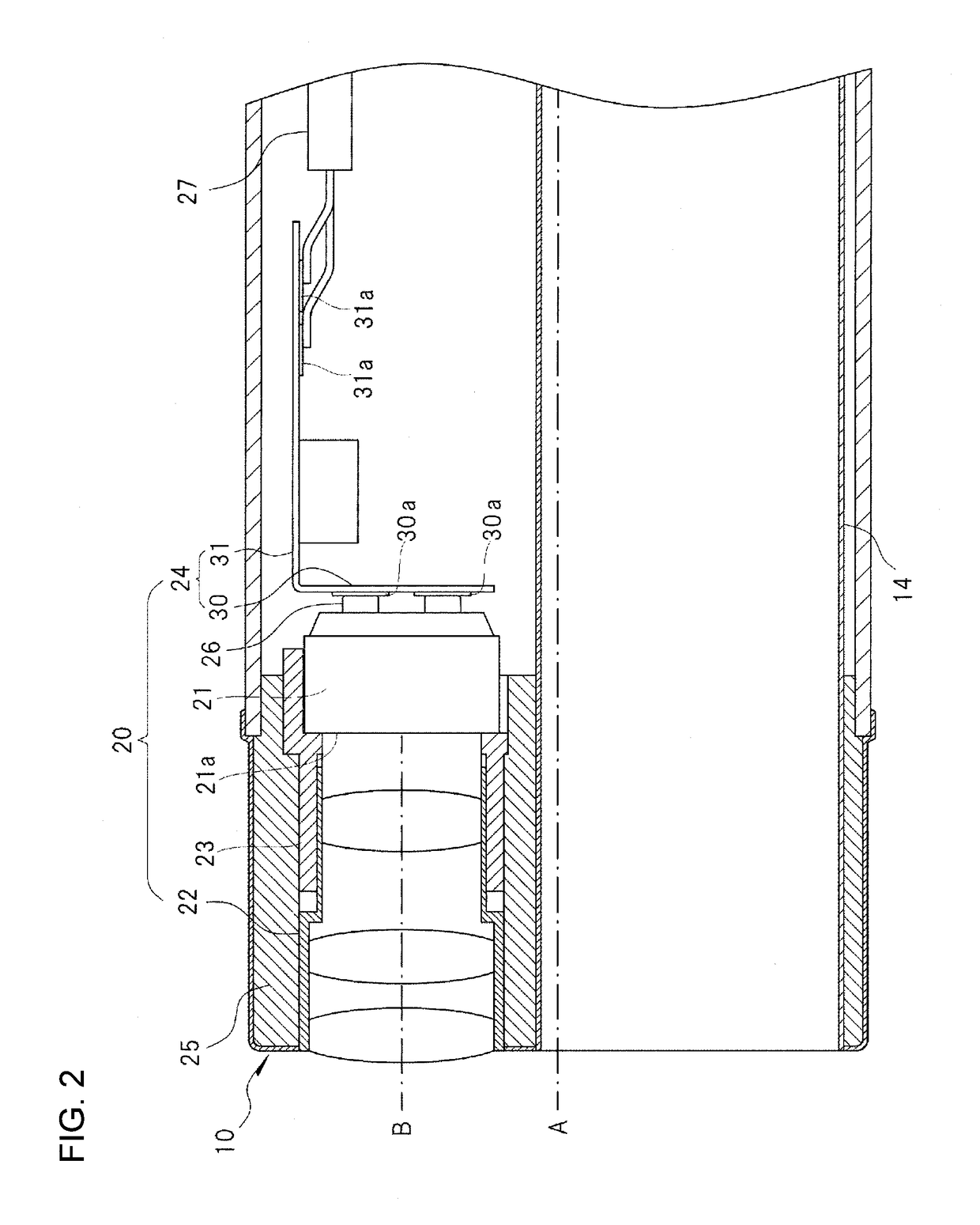
[0051]The front end portion 10 is provided with an illumination optical system, an imaging device, an imaging optical system, etc. The illumination optical system emits illumination light for lighting a part to be observed. The imaging device and the imaging ...


PUM


Abstract

An endoscope includes an image sensor that is provided at a front end portion of an insertion portion of the endoscope so that an image receiving surface of the image sensor is disposed to cross a longitudinal axis of the insertion portion; a sensor holder that surrounds an outer circumference of the image sensor and holds the image sensor; and a circuit board including a sensor connection portion and an electric wire connection portion as defined herein; the image sensor is held by the sensor holder as defined herein; the sensor connection portion and the electric wire connection portion are connected to each other as defined herein; and an outside edge of a connection site between the sensor connection portion and the electric wire connection portion is located as defined herein.

Description

CROSS-REFERENCE TO RELATED APPLICATIONS[0001]This application claims the benefit of Japanese Patent Application JP 2015-203816, filed Oct. 15, 2015, the entire content of which is hereby incorporated by reference, the same as if set forth at length.FIELD OF THE INVENTION[0002]The present invention relates to an endoscope.BACKGROUND OF THE INVENTION[0003]An imaging device to be mounted on a front end portion of an insertion portion of an endoscope is generally provided with an image sensor and a circuit board on which the image sensor is mounted. A plurality of electric wires inserted into the insertion portion are connected to the circuit board. A flexible circuit board that can be folded to be comparatively small is typically used as the circuit board. However, a rigid circuit board may be used in some case (for example, see JP-A-2013-123628, JP-A-2014-204275 and JP-A-2015-62555).SUMMARY OF THE INVENTION[0004]There is a request for further reduction in diameter of an insertion port...

Claims


Application Information

Patent Timeline
IPC IPC(8): G02B23/24H04N5/225
CPCG02B23/2484H04N2005/2255G02B23/2469H04N5/2253H04N23/555H04N23/56H04N23/54
Inventor KITANO, RYOYASHIRO, TAKASHI
Owner FUJIFILM CORP
Learn More