Patient support apparatus

a technology for supporting devices and patients, which is applied in the direction of fluid mattresses, sofas, transportation and packaging, etc., can solve the problems of not providing prior art also fails to provide a touch screen display, and fails to disclose a system, so as to reduce the number of operations and quickly switch between functions

Active Publication Date: 2006-05-18
STRYKER CORP
View PDF20 Cites 197 Cited by
  • Summary
  • Abstract
  • Description
  • Claims
  • Application Information

AI Technical Summary

Benefits of technology

[0009] The present invention provides a patient support apparatus comprising a mattress having a plurality of therapeutic devices for carrying out a plurality of therapeutic functions. A control system is in operative communication with the plurality of therapeutic devices to control the devices. The control system includes a touch-screen display segmented into a main menu portion and a data window portion. The main menu portion has at least one touch selectable button corresponding to each of the therapeutic functions and the data window portion displays at least one adjustable operating parameter

Problems solved by technology

The prior art, however, fails to provide a mattress having multiple therapeutic devices for carrying out multiple therapeutic functions with a controller having a touch-screen display that is segmented into a main menu portion and a data window portion to easily select between the therapeutic functions.
The prior art also fails to provide a touch-screen display that allows an operator to change a display language, to select between multiple alarm styles, or to quickly access a therapy history screen that recalls the therapies performed by the mattress in rolling 12-hour or 24-hour increments.
In addition, the prior art fails to disclose a system for automatically activating a backlight of the touch-screen display as an operator approaches the touch-screen display.

Method used


Image

  • Patient support apparatus
  • Patient support apparatus
  • Patient support apparatus

Examples


Embodiment Construction

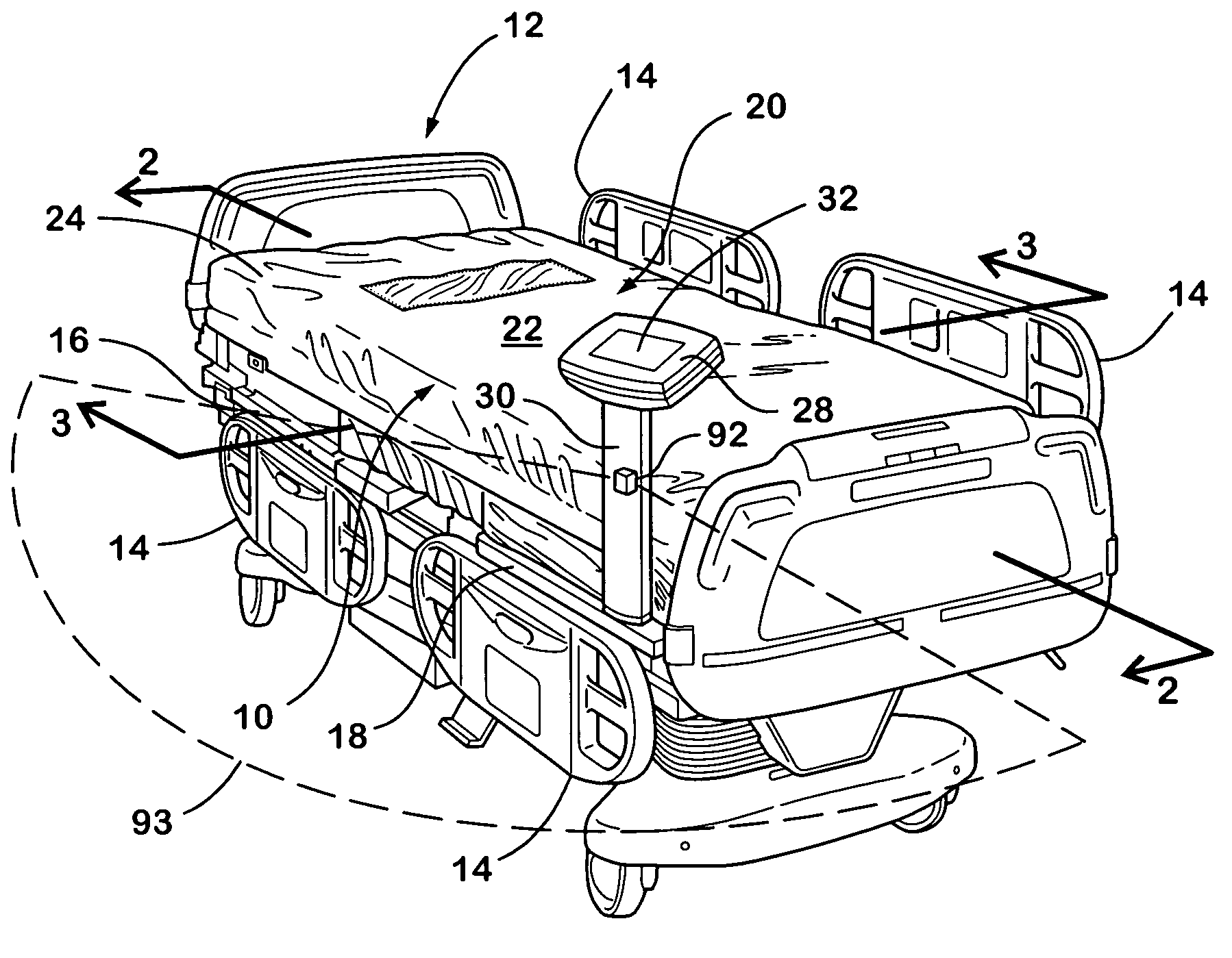
[0052] Referring to the Figures, wherein like numerals indicate like or corresponding parts throughout the several views, a patient support apparatus of the present invention is generally shown at 10.

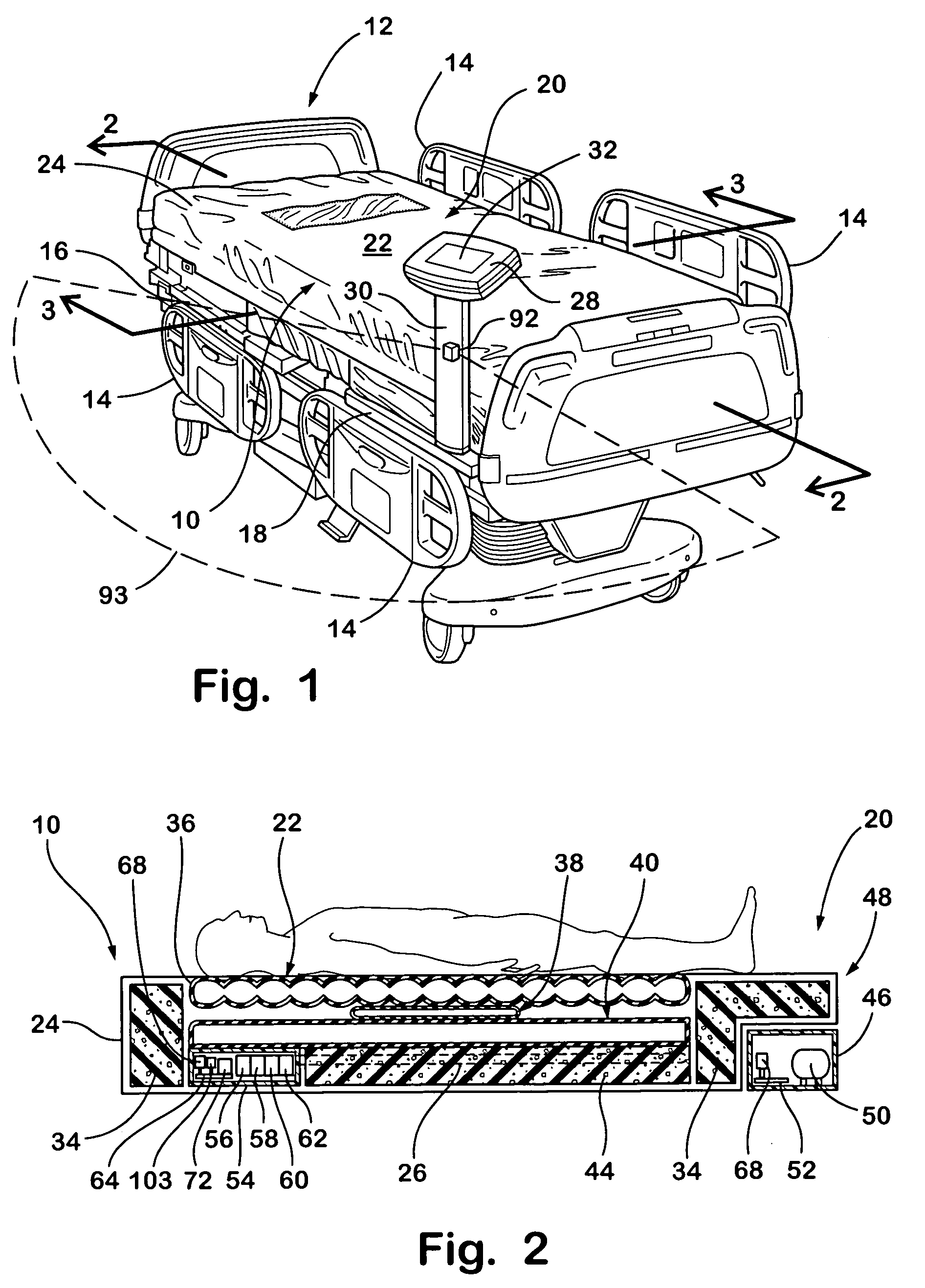
[0053] Referring to FIG. 1, the patient support apparatus 10 of the present invention is shown in combination with a mobile hospital bed frame 12. As illustrated, the hospital bed frame 12 typically includes a plurality of side rails 14 that can be lowered for patient transfer and raised to confine a patient. The hospital bed frame 12 can also include a plurality of adjustable sections including an adjustable head section 16 that is pivotally adjustable relative to a main body section 18 of the bed frame 12 to allow the patient to sit up while eating or visiting with family.

[0054] Still referring to FIG. 1, the patient support apparatus 10 comprises a self-contained mattress 20 having a patient support surface 22. The mattress 20 is referred to as being self-contained since most of th...


PUM


Abstract

A patient support apparatus is provided. The patient support apparatus includes a plurality of therapeutic devices including a rotation device and a percussion-vibration device for carrying out rotation, percussion, and vibration therapy for a patient. The patient support apparatus includes a control system for controlling operation of the plurality of therapeutic devices. The control system comprises a touch-screen display segmented into a main menu portion and a data window portion. The therapeutic functions are represented by touch selectable buttons on the main menu portion. When any of these buttons are selected, a plurality of adjustable operating parameters appears in the data window portion. At the same time, the buttons corresponding to the therapeutic functions in the main menu portion remain visible such that an operator can easily select another therapeutic function. A method of tracking the therapeutic functions performed is provided. A rotation monitoring system and temperature control system of the patient support apparatus are provided. A display activation system is also provided.

Description

[0001] This application claims the benefit of U.S. provisional patent application Ser. No. 60 / 623,653, filed Oct. 29, 2004, the advantages and disclosure of which are hereby incorporated by reference.FIELD OF THE INVENTION [0002] The present invention relates to a patient support apparatus configured to provide multiple therapeutic functions. More specifically, the present invention relates to the patient support apparatus comprising a mattress having multiple therapeutic devices for carrying out the therapeutic functions and a main control system for controlling these therapeutic devices. BACKGROUND OF THE INVENTION [0003] Patient support systems are well known in the art for providing therapy to a patient. A typical patient support apparatus comprises a mattress having a plurality of air bladders for supporting the patient, a percussion device that alternates inflation and deflation of air bladders to provide percussion and vibration therapy to the patient, and a rotation device, ...

Claims


Application Information

Patent Timeline
IPC IPC(8): A47C27/10A61G7/057A61G7/008
CPCA61G7/00A61G7/001A61G7/018A61G2203/46A61G2007/05784A61G2203/36A61G2203/42A61G7/05769A61G7/05784
Inventor BLANCHARD, FREDERICK WILLIAMTHOMPSON, JEFFERY JOSEPHWROBLESKI, DENNIS JOHNSMITH, MICHAEL STERLING
Owner STRYKER CORP
Why Eureka
Try Eureka