Fixing device
a fixing device and fixing roller technology, applied in the field of fixing devices, can solve the problems of bending deformation, damage to the end elastic deformation of the outside roller of the fixing roller, etc., and achieve the effect of maintaining the durability of the fixing roller
- Summary
- Abstract
- Description
- Claims
- Application Information
AI Technical Summary
Benefits of technology
Problems solved by technology
Method used
Image
Examples
first embodiment
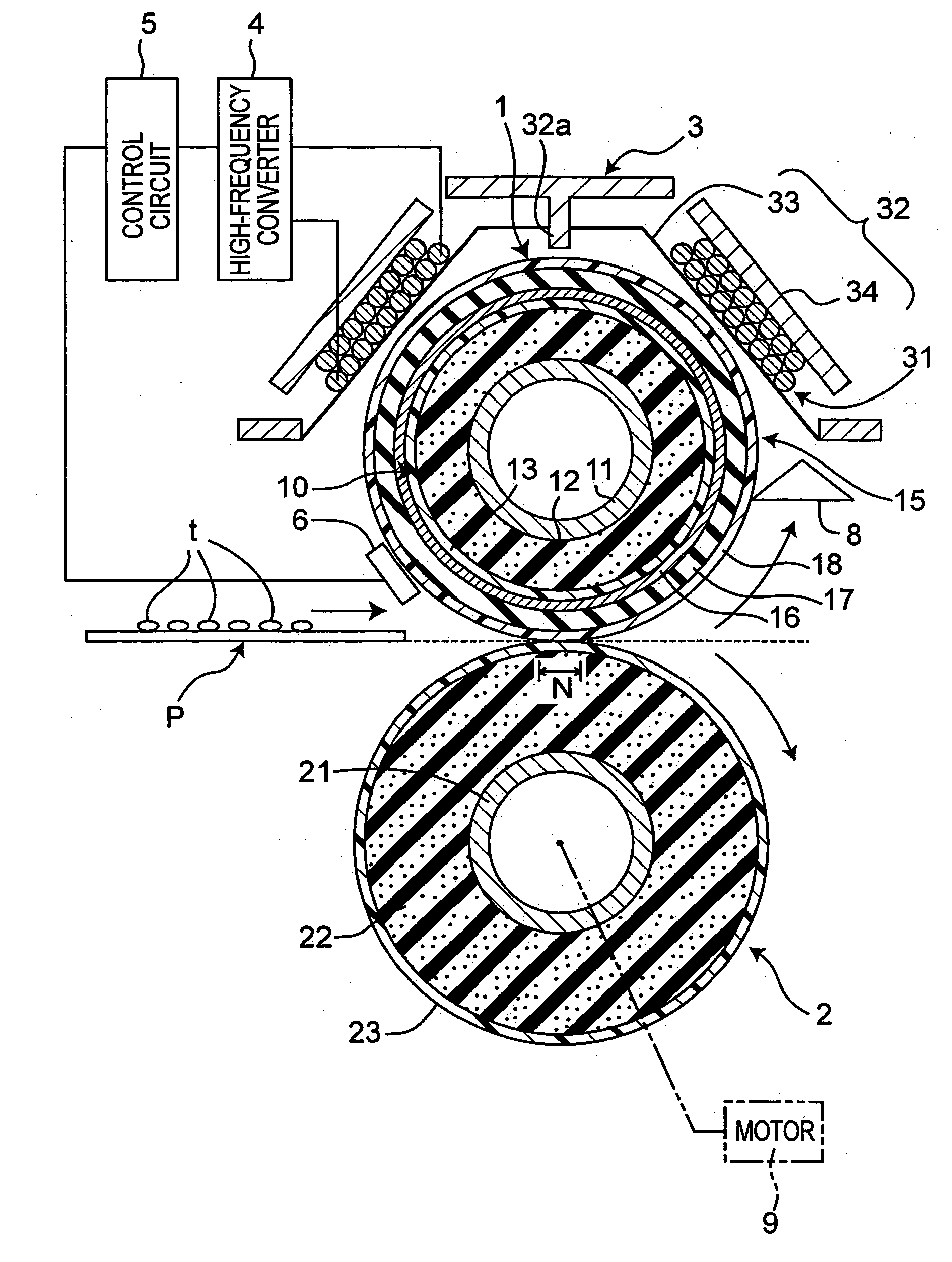
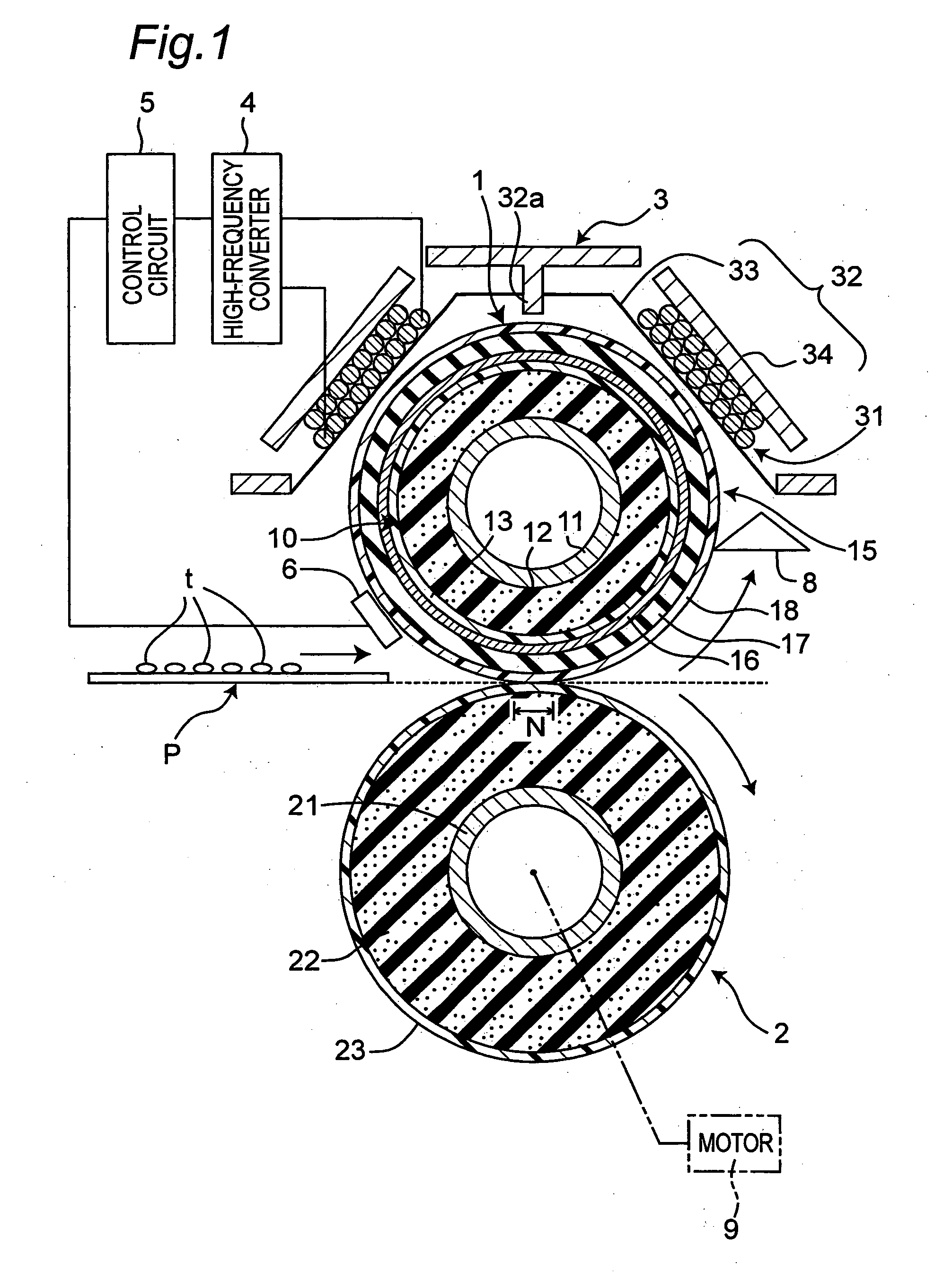
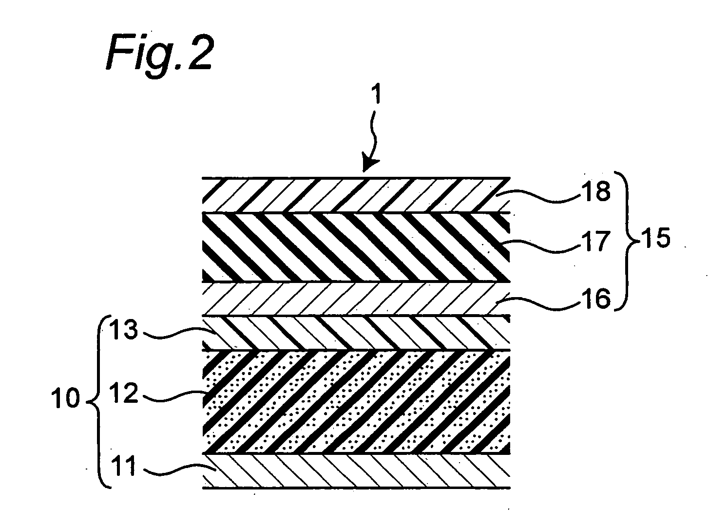
[0035]FIG. 1 is a cross sectional configuration view of a fixing device according to a first embodiment of the present invention. As shown in FIG. 1, the fixing device, which is of induction heating type, includes an electromagnetic induction heating-type fixing roller 1, a pressure roller 2 which contacts with the fixing roller 1 to form a nip N, and a magnetic flux generation means 3 disposed outside of the fixing roller 1 for generating magnetic flux.
[0036] The fixing roller 1 generates heat by virtue of magnetic flux from the magnetic flux generation means 3. Thereafter, a recording material P carrying an unfixed image t is passed through between the fixing roller 1 and the pressure roller 2. Thereby, the unfixed image t is melted and fixed (heated and fixed) to the recording material P while the recording material P is held and transported by the nip N.
[0037] The fixing device, together with an imaging means (unshown) for forming the unfixed image t on the recording material ...
second embodiment
[0087]FIG. 4 shows a fixing device according to a second embodiment of the present invention. Description is given of the difference from the first embodiment. In the second embodiment, an edge 29 of the pressure roller 2 is not in a straight line form but in a wave form. Specifically, the edge 29 of the pressure roller 2 is a meandering curved line when viewed from a direction orthogonal to an axis of the pressure roller 2.
[0088] Thus, the outside roller 15 in the fixing roller 1 is less susceptible to developing creases and flaws when the pressure roller 2 presses the fixing roller 1 because the edge 29 of the pressure roller 2 is a meandering curved line. That is, damage is prevented in a boundary portion between the nip formation region I and the outside roller free region II as shown in FIG. 3.
[0089] On the contrary, in the case where the edge 29 of the pressure roller 2 is a straight line when viewed from the direction orthogonal to the axis of the pressure roller 2, the out...
third embodiment
[0090]FIG. 5 shows a fixing device according to a third embodiment of the present invention. Description is given of the difference from the first embodiment. In the third embodiment, an edge between the end face 28 and the contact face 25 in the pressure roller 2 is formed into a convex curve face 26. In other words, the edge of the pressure roller 2 is roundly chamfered.
[0091] Since the edges of the pressure roller 2 have the convex curve face 26, it becomes difficult to form creases and flaws in the outside roller 15 of the fixing roller 1 when the pressure roller 2 presses the fixing roller 1. In other words, damage is prevented in the boundary portion between the nip formation region I and the outside roller free region II as shown in FIG. 3.
PUM
 Abstract
Description
Claims
Application Information
 - Generate Ideas
- Intellectual Property
- Life Sciences
- Materials
- Tech Scout
- Unparalleled Data Quality
- Higher Quality Content
- 60% Fewer Hallucinations
Browse by: Latest US Patents, China's latest patents, Technical Efficacy Thesaurus, Application Domain, Technology Topic, Popular Technical Reports.
© 2025 PatSnap. All rights reserved.Legal|Privacy policy|Modern Slavery Act Transparency Statement|Sitemap|About US| Contact US: help@patsnap.com


