
Optical transmitting apparatus, method of increasing the number of paths of the apparatus, and optical switch module for increasing the number of paths of the apparatus

a technology of optical transmission apparatus and optical switch module, which is applied in the direction of multiplex communication, data switching network, instruments, etc., can solve the problems of large size of the whole apparatus, large number of optical fiber patch cords to be connected to the switch fabric, and the number of ports, etc., to achieve the effect of reducing the initial introduction cost of the optical transmitting apparatus, increasing the number of transmission paths, and increasing the number of drop/add signal lights

Inactive Publication Date: 2006-05-11
FUJITSU LTD
View PDF7 Cites 84 Cited by
  • Summary
  • Abstract
  • Description
  • Claims
  • Application Information

AI Technical Summary

Benefits of technology

[0023] The invention has been achieved in consideration of such problems and an object of the invention is to realize flexible function expansion of an optical transmitting apparatus while largely reducing the number of wires (optical fiber patch cords) (reducing the size of the apparatus) necessary in an optical transmitting apparatus dealing with a plurality of transmission paths such as an optical cross connect apparatus and largely reducing the number of spare ports required for future increase in the number of transmission paths.

Problems solved by technology

The conventional optical cross connect apparatus has, however, the following problems.
(1) Problems on the Number of Ports, Cost, and Size in the Conventional Node Configuration
Accordingly, the size of the whole apparatus becomes large and the number of optical fiber patch cords to be connected to the switch fabric 102 also becomes enormous.
A problem occurs such that it becomes very inconvenient to house and manage the optical fiber patch cords.
For example, if the number of input / output wavelengths (M) increases, the number of input / output ports necessary for the optical switches and the optical combiners also increases, so that the apparatus scale and cost increase.
In particular, since the number of input / output ports which can be provided for the optical switches and optical combiners is limited in the present techniques, in the case where optical signals of tens of wavelengths are multiplexed per highway, the technique cannot be realized.
Moreover, also in the case of addressing future increase in the number of input / output transmission paths and increase in drop / add signal lights, input / output ports of the predictable maximum number of wavelengths have to be prepared for spare (unused) optical switch and optical combiner, so that the apparatus becomes large-scaled and expensive from the initial operation.
Moreover, in the case where upgrading to the number of degrees over expectation is requested, the request cannot be addressed.
The technique of Patent Document 1 also has the same problem.

Method used


Image

  • Optical transmitting apparatus, method of increasing the number of paths of the apparatus, and optical switch module for increasing the number of paths of the apparatus
  • Optical transmitting apparatus, method of increasing the number of paths of the apparatus, and optical switch module for increasing the number of paths of the apparatus
  • Optical transmitting apparatus, method of increasing the number of paths of the apparatus, and optical switch module for increasing the number of paths of the apparatus

Examples


first embodiment

A. First Embodiment

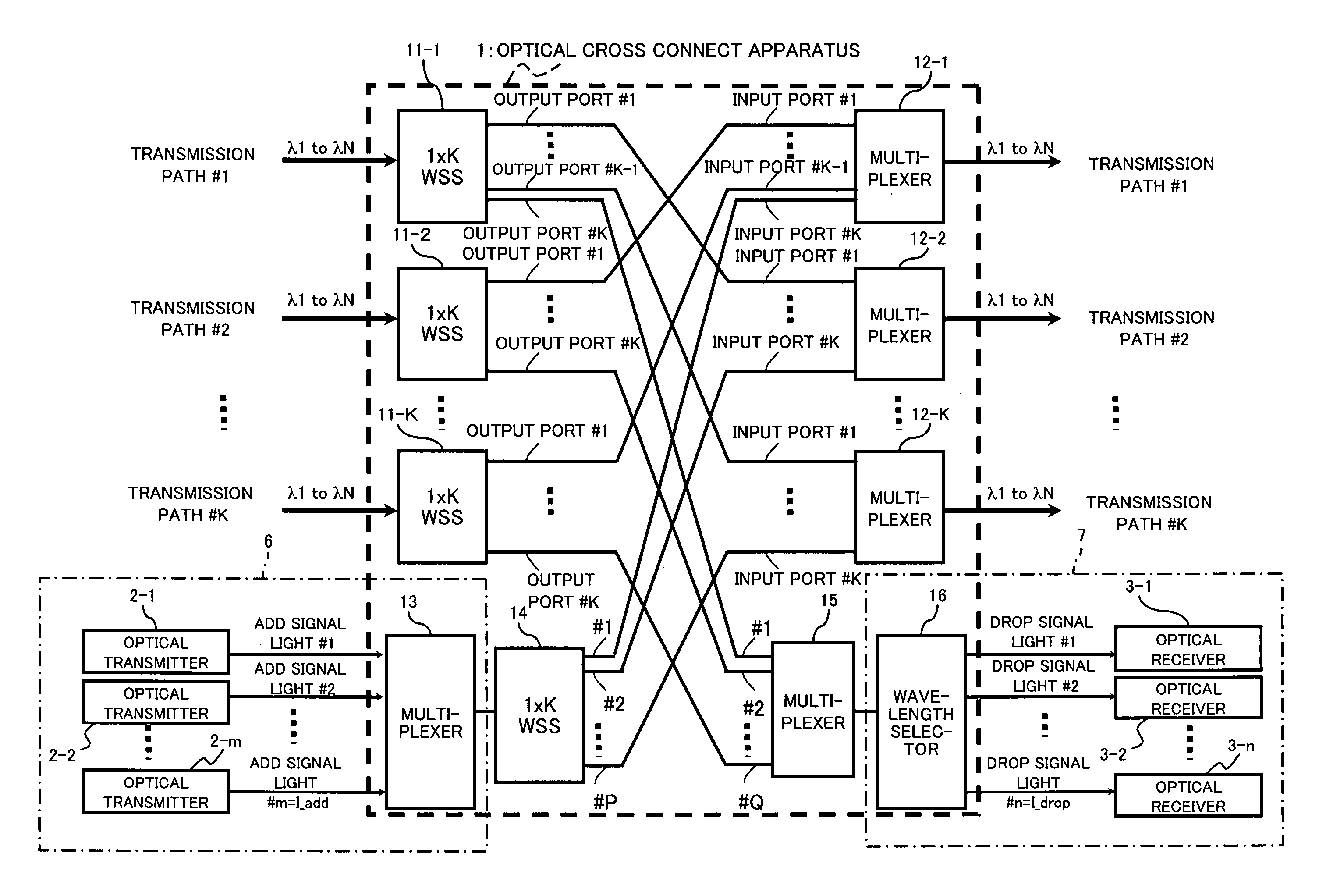
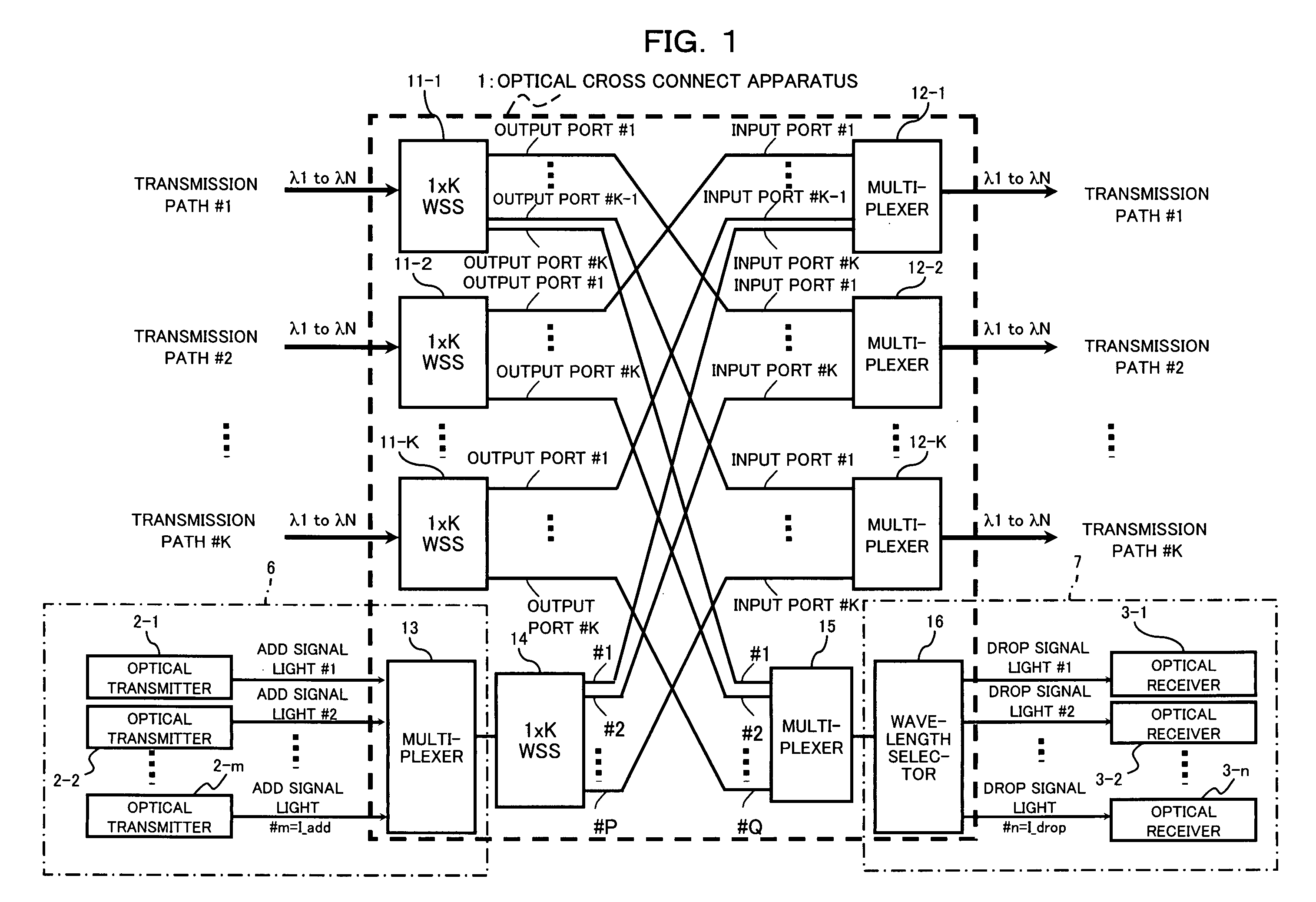
[0071]FIG. 1 is a block diagram showing the configuration of an optical cross connect apparatus (optical transmitting apparatus) of a first embodiment of the invention. An optical cross connect apparatus (hereinbelow, also called a node) 1 shown in FIG. 1 is an apparatus to which wavelength division multiplex signal lights (WDM lights) of maximum N wavelengths (λ1 to λN, where N denotes an integer of 2 or larger) are input from K pieces (K: an integer of 2 or larger) of transmission paths (input light transmission paths) #1 to #K and which can output WDM lights of maximum N wavelengths to each of K pieces of transmission paths (output light transmission paths) #1 to #K. When the number of add signal light wavelengths to be output (added) to any of the output light transmission paths #1 to #K are m (=I_add), the number of drop signal light wavelengths to be dropped from any of the input light transmission paths #1 to #K are n (=I drop), the minimum integer of integ...

second embodiment

B. Description of Second Embodiment

[0134]FIGS. 11A to 11C are diagrams showing images of an optical node in-service upgrading method (path adding method) according to a second embodiment of the invention. For example, as shown in FIG. 1A, in the case of upgrading an ROADM node (optical transmitting apparatus) 1C of 2 degrees to an optical cross connect (WXC) node of 3 degrees during service operation, as shown in FIG. 11B, by connecting a modular switch (optical switch module) 5-1 to an idle (unused) port for upgrading which is prepared in advance for the ROADM node 1C, the number of paths (transmission paths) is increased. In the case of also preliminarily providing the modular switch 5-1 with an idle (unused) port for upgrading and further increasing the number of paths to construct a WXC node having 4 degrees from the node having 3 degrees, as shown in FIG. 11C, by connecting a modular switch 5-2 having an idle port for upgrading to the idle port of the modular switch 5-1, the nu...


PUM


Abstract

An optical transmitting apparatus is configured such that K pieces of output ports of optical path switching units whose input port is connected to k-th input transmission path are connected to first to K-th output transmission paths except for the k-th output transmission path and to the k-th input port of a dropping unit, and the optical path switching units and the dropping unit outputs light of wavelength which is part or all of WDM light received from said input port from a specific output port, and can output light having a wavelength different from that of the light output from said specific output port from an output port different from said specific output port. Accordingly, while largely reducing the number of optical fiber patch cords necessary in an optical transmitting apparatus and largely reducing the number of spare ports, the flexible expansion of apparatus function can be realized.

Description

CROSS REFERENCE TO RELATED APPLICATIONS [0001] This application is based on and hereby claims priority to Japanese Application No. 2004-326556 filed on Nov. 10, 2004 in Japan, the contents of which are hereby incorporated by reference. BACKGROUND OF THE INVENTION [0002] (1) Field of the Invention [0003] The present invention relates to an optical transmitting apparatus, a method of increasing the number of paths of the apparatus, and an optical switch module for increasing the number of paths of the apparatus and, more particularly, to a technique suitable for use in an optical transmitting apparatus having an optical cross connecting function and an optical add-drop function. [0004] (2) Description of Related Art [0005] In a wavelength division multiplex (WDM) optical transmitting system, an optical cross connect function of changing the destination of input light every wavelength of WDM light and an optical add and drop multiplexing (OADM) function of outputting (adding) add signa...

Claims


Application Information

Patent Timeline
IPC IPC(8): H04J14/00H04B10/27G02B26/08H04B10/291H04J14/02H04L12/70H04Q3/52
CPCH04J14/0209H04J14/0212H04J14/0213H04J14/0217H04Q11/0005H04Q2011/0009H04Q2011/0016H04Q2011/0024H04Q2011/003H04Q2011/0032
Inventor MIURA, AKIRAOOI, HIROKIHOSHIDA, TAKESHITERAHARA, TAKAFUMI
Owner FUJITSU LTD
Learn More