
Programmable display device

a display device and programmable technology, applied in the direction of electrical controllers, program control, instruments, etc., can solve the problems of complex management of screens in the project file, inability to quickly change production lines according to frequent product changes, etc., and achieve the effect of easy plurality managemen

Active Publication Date: 2006-05-11
SCHNEIDER ELECTRIC JAPAN HLDG LTD
View PDF8 Cites 13 Cited by
  • Summary
  • Abstract
  • Description
  • Claims
  • Application Information

AI Technical Summary

Benefits of technology

[0011] The present invention is made in view of the foregoing problems, and its object is making it easy to manage a plurality of project files.
[0014] As a result, the screen data groups are switched and set, and thereby the screen data groups can be dispersed and managed in internal and external storage sections. Therefore, it is unnecessary to cause one screen data group to include screens corresponding to all kinds of products to respond to a variety of products by a single production line for the purpose of limited production of a wide variety of products. As such, it is sufficient to provide screen data groups corresponding to each product.

Problems solved by technology

However, in recent limited production of a wide variety of products, in order to deal with a wide variety of products by a single production line, it is necessary for a single project file to include screens corresponding to production lines of all kinds of products.
As a result, multiple screens are included in a single project file, resulting in such an inconvenience that a management of screens in the project file becomes complex, and a memory capacity for storing the project file in the programmable display device is used up.
However, in such a method, it takes much time to transfer the project file, and therefore it is impossible to promptly change production lines according to frequent changes of products.

Method used


Image

  • Programmable display device
  • Programmable display device
  • Programmable display device

Examples


Embodiment Construction

[0026] An embodiment of the present invention is described below with reference to FIGS. 1 through 9.

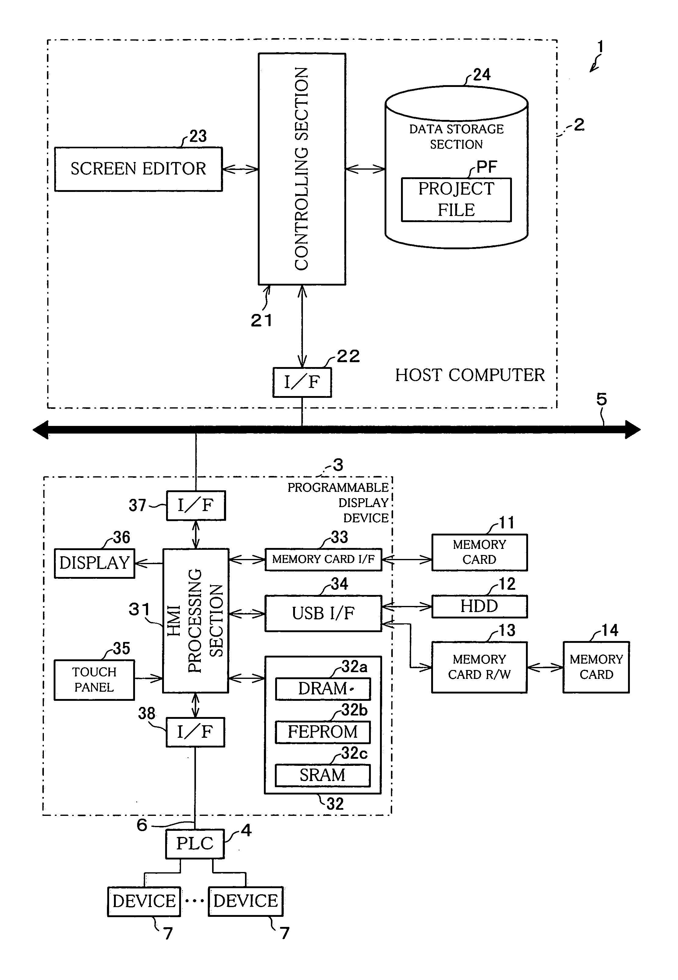
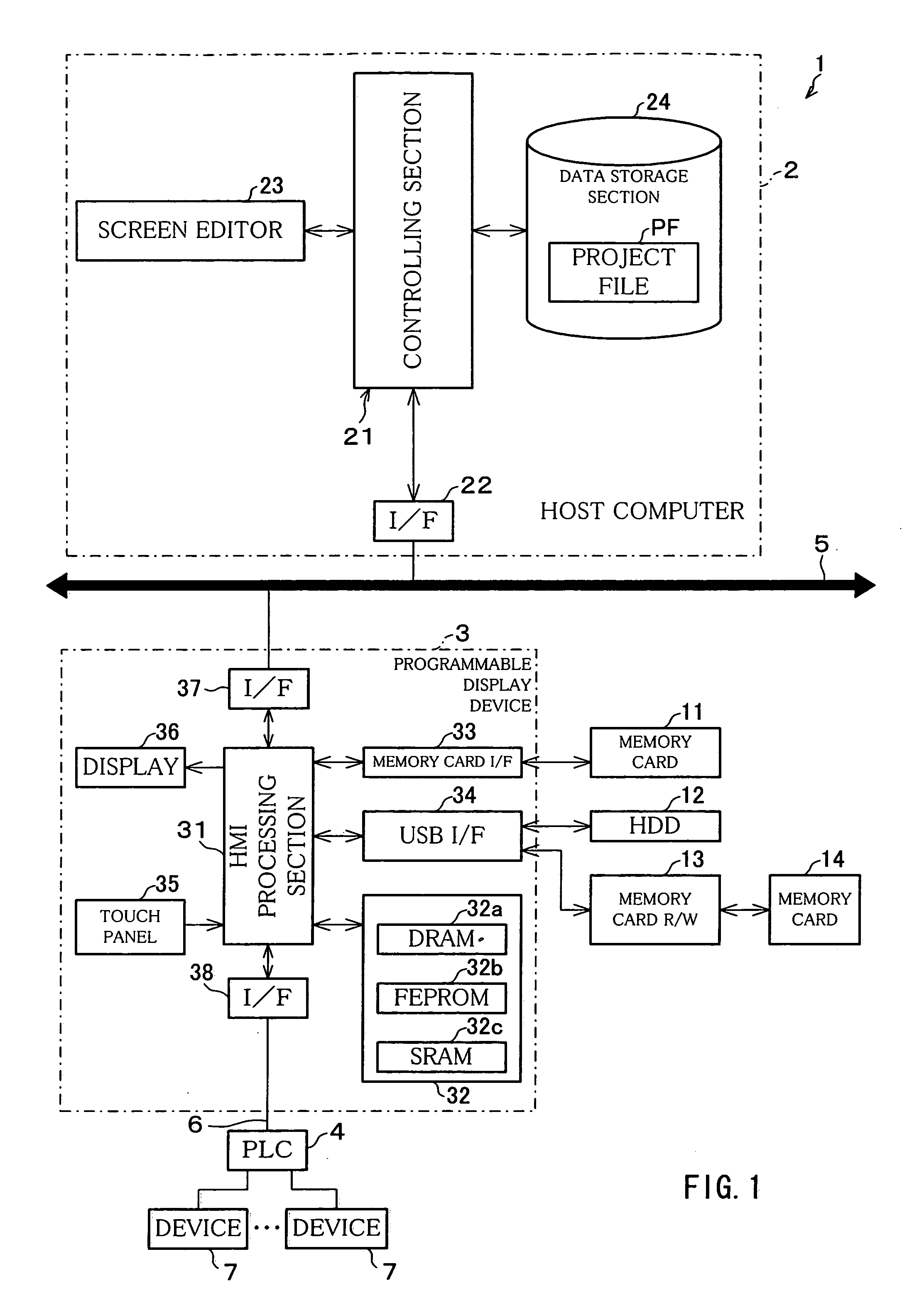
[0027] As illustrated in FIG. 1, a controlling system 1 according to the present embodiment includes a host computer 2, a programmable display device 3, a PLC 4, a common network 5, an exclusive network 6, and a device 7.

[0028] The host computer 2 and the programmable display device 3 are connected with each other via the common network 5. On the other hand, the programmable display device 3 and the PLC 4 are connected with each other via the exclusive network 6. The common network 5 is a network such as a local area network (LAN) constituted of Ethernet™ and the like, by which it is possible to communicate through use of a common communication protocol. The exclusive network 6 is a network constituted of a serial cable and the like, by which it is possible to communicate through use of a communication protocol exclusive to the PLC 4 (an exclusive communication protocol). Because t...


PUM


Abstract

A programmable display device selects and displays one screen data item from one of screen data groups each constituted of a plurality of screen data items indicative of control conditions. Further, the programmable display device includes a selection information forming section and a screen data group setting section. The selection information forming section is included in a project setting processing section, and based on screen data group information concerning the screen data groups, forms selection information by which one of the screen data groups is selected. The screen data group setting section is included in the project setting processing section, and sets, as a screen data group to be used, the one of the screen data groups which is selected based on the selection information.

Description

[0001] This non-provisional application claims priority under 35 U.S.C. § 119(a) on Patent Application No. 2004 / 322659 filed in Japan on Nov. 5, 2004, the entire contents of which are hereby incorporated by reference. FIELD OF THE INVENTION [0002] The present invention relates to a programmable display device that is able to manage many screens easily. BACKGROUND OF THE INVENTION [0003] A programmable display device is an operational display device having an interface with a host controller (PLC), and having functions such as for displaying an operating condition of a device connected to the host controller and receiving from a screen an operational input for providing control instructions to the device. Generally, a programmable display device has a graphical display function, and accordingly can display a console, a switch, a display lamp and the like, so as to serve as an operating terminal in a controlling system. [0004] A screen displayed on such a programmable display device c...

Claims


Application Information

Patent Timeline
IPC IPC(8): G09G5/00
CPCG05B2219/13171G05B2219/23406H04L67/36H04L67/75
Inventor OGAWA, MASAKI
Owner SCHNEIDER ELECTRIC JAPAN HLDG LTD
Learn More