
Linear motor with a segmented stator

Active Publication Date: 2006-05-11
ETEL SA
View PDF11 Cites 8 Cited by
  • Summary
  • Abstract
  • Description
  • Claims
  • Application Information

AI Technical Summary

Benefits of technology

[0011] The result of the characteristics of the present invention is a rigid fastening at the level of the joint between two adjacent stator pieces, which makes it possible to prevent vibrations of the stator during operation and to maintain proper contact between the general lateral surfaces at the joint between two stator pieces.

Problems solved by technology

The rigidity of such an assembly is not properly assured.
The dynamic behavior of the stator can therefore be disturbed, which is harmful in several applications wherein the moving part is subject to large accelerations.
The segmented stator proposed in this document has another major drawback in that the tooth formed at the level of the joint between two stator pieces does not have a flat and horizontal lower surface like that of the other teeth.
This increases the reluctance effect of the stator and reduces its efficiency.

Method used


Image

  • Linear motor with a segmented stator
  • Linear motor with a segmented stator
  • Linear motor with a segmented stator

Examples


Embodiment Construction

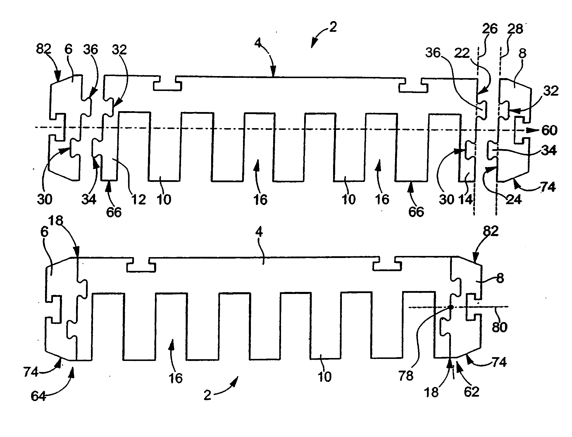
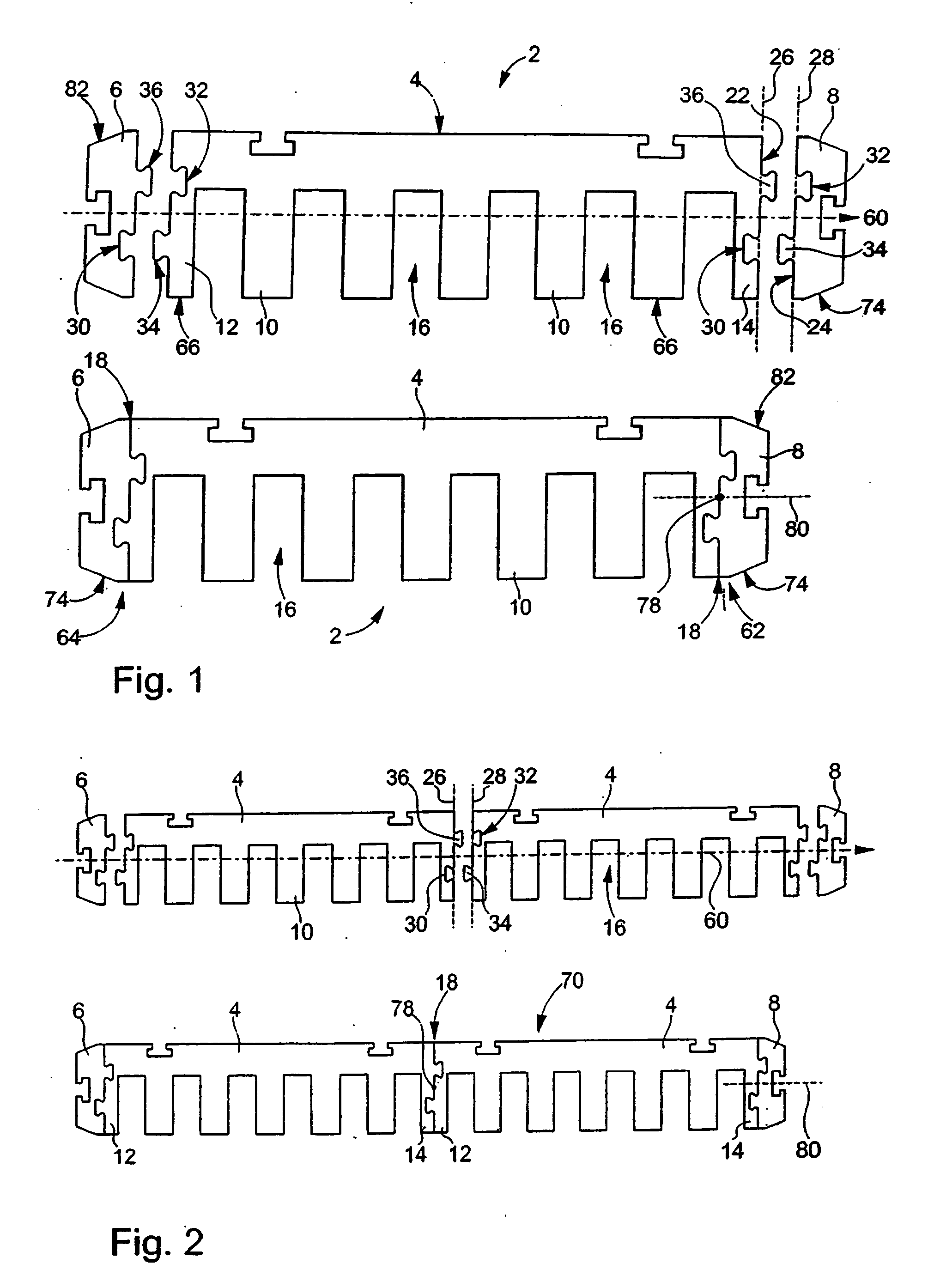
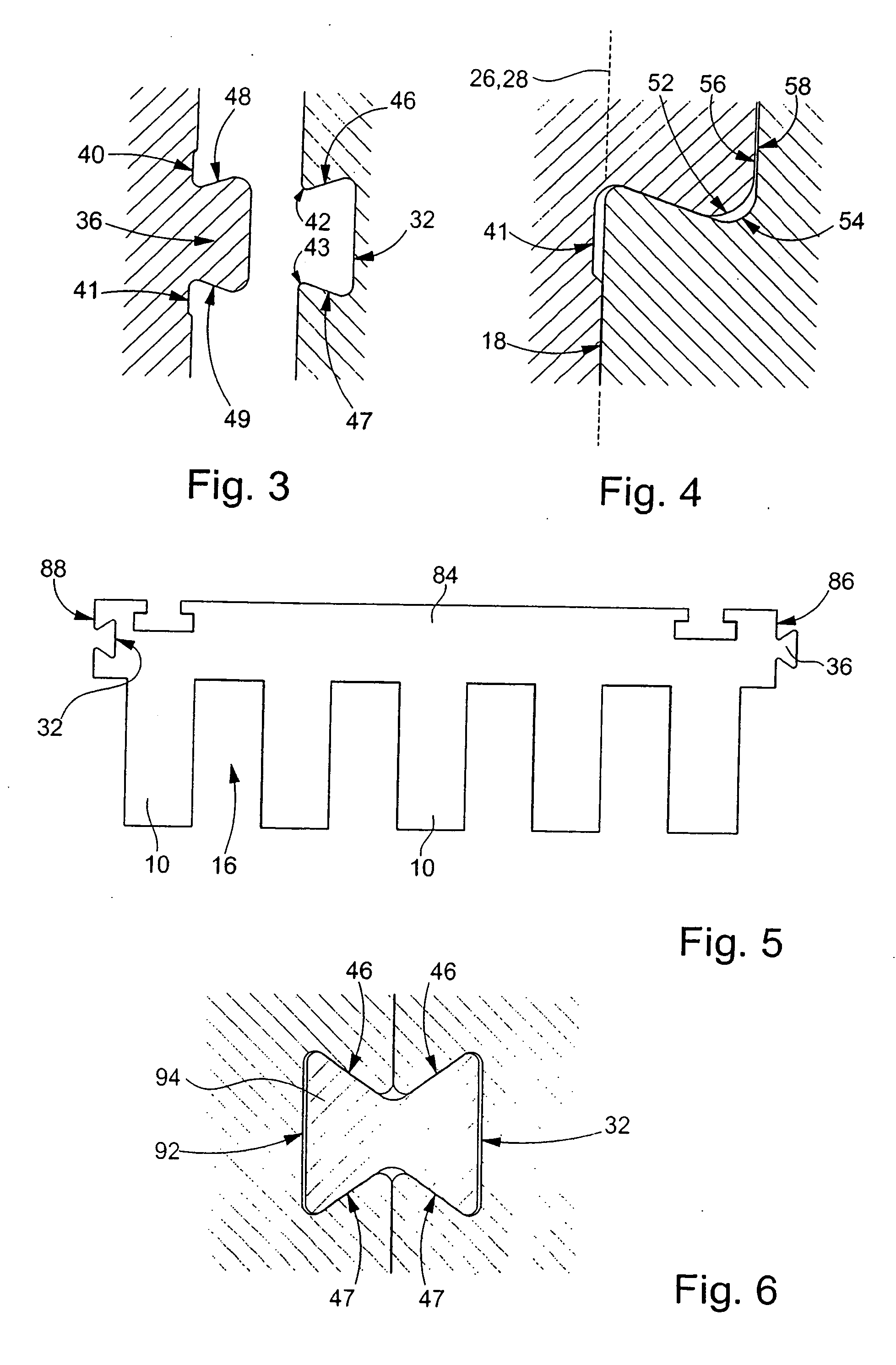
[0022] A first preferred embodiment of a linear motor according to the present invention will be described below with the help of FIGS. 1 through 4.

[0023] Since the present invention concerns the embodiment of the stator of the moving part of the linear motor, the various figures only schematically represent this stator. One skilled in the art will be familiar with the parts of the linear motor that are not represented, particularly the magnetic track forming a fixed inductor that is disposed opposite the teeth of the stator and the windings that are provided inside the slots defined by the stator.

[0024] The stator 2 represented in FIG. 1 is segmented into three distinct pieces: an elemental piece 4 forming the body of the stator and two end parts 6 and 8 disposed on either side of the piece 4, to which they are joined by fastenings which are specific subjects of the present invention.

[0025] The stator piece 4 forming the body of the stator includes a plurality of whole teeth 10 ...


PUM


Abstract

A linear motor having a fixed inductor and a moving part including windings and a stator. The stator includes a plurality of teeth defining a plurality of slots into which the windings are inserted, the stator being segmented into a first piece and a second piece adjacent to the first piece. Ajoint is defined between the first piece and the second piece. A fastening fastens the first piece to the second piece, wherein the fastening includes a recess disposed in a first lateral surface of the first piece located at the joint, wherein the recess opens exclusively onto the lateral surface and defines at least one locking surface. A complementary part formed from the second piece and which engages the at least one locking surface so as to hold the first lateral surface and a second lateral surface of the second piece against one another.

Description

[0001] Applicant claims, under 35 U.S.C. § 119, the benefit of priority of the filing date of Nov. 8, 2004 of a Swiss patent application, copy attached, Serial Number 01831 / 04, filed on the aforementioned date, the entire contents of which is incorporated herein by reference. BACKGROUND OF THE INVENTION [0002] 1. Field of the Invention [0003] The present invention concerns a linear motor whose moving part has a stator formed of several pieces assembled in the longitudinal direction of this moving part. [0004] 2. Discussion of Related Art [0005] A linear motor stator, segmented into several pieces or parts that are assembled once these pieces or parts have been produced, has several advantages. [0006] First, it is possible to define a basic piece of elemental length for the body of the stator. During the final assembly of the stator, it is possibly to vary its length in accordance with the type of linear motor built or in accordance with the application for which it is intended, by a...

Claims


Application Information

Patent Timeline
IPC IPC(8): H02K41/00
CPCH02K1/16H02K1/182H02K41/031H02K1/148
Inventor MOREL, JEAN-PIERRE
Owner ETEL SA
Learn More