
Ejector with multi-ejection pins

Inactive Publication Date: 2006-05-04
IND TECH RES INST
View PDF10 Cites 4 Cited by
  • Summary
  • Abstract
  • Description
  • Claims
  • Application Information

AI Technical Summary

Benefits of technology

[0011] The primary objective of the invention is therefore to specify an ejector with multi-ejection pins that is adapted for a semiconductor post-process and can lift a plurality of dies simultaneously, in order to increase the efficiency of the relevant equipment and to improve commercial benefits.
[0012] The secondary objective of the invention is therefore to specify an ejector with multi-ejection pins; the ejector can select ejector pins individually for die choice, so as to save materials and increase manufacturing efficiency.

Problems solved by technology

However, this conventional device can only single arrange one pin at a time and as such is incompatible with mass production methods.
Additionally, the conventional device is obviously complicated and huge and a number of the devices used for lifting multiple dies cannot operate together simultaneously.
This conventional device can also only arrange a single pin at a time and as such is incompatible with mass production methods.

Method used


Image

  • Ejector with multi-ejection pins
  • Ejector with multi-ejection pins
  • Ejector with multi-ejection pins

Examples


Embodiment Construction

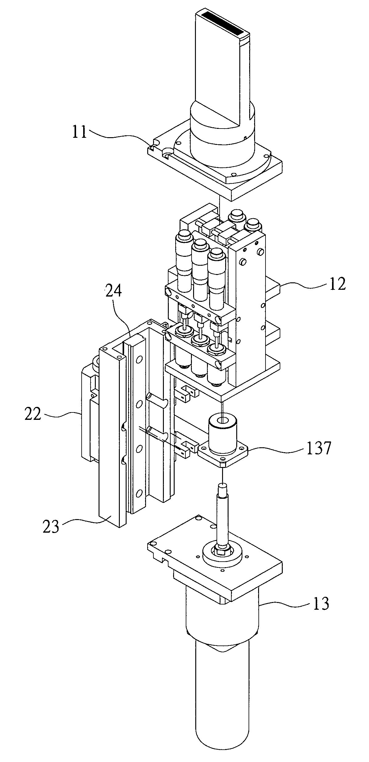
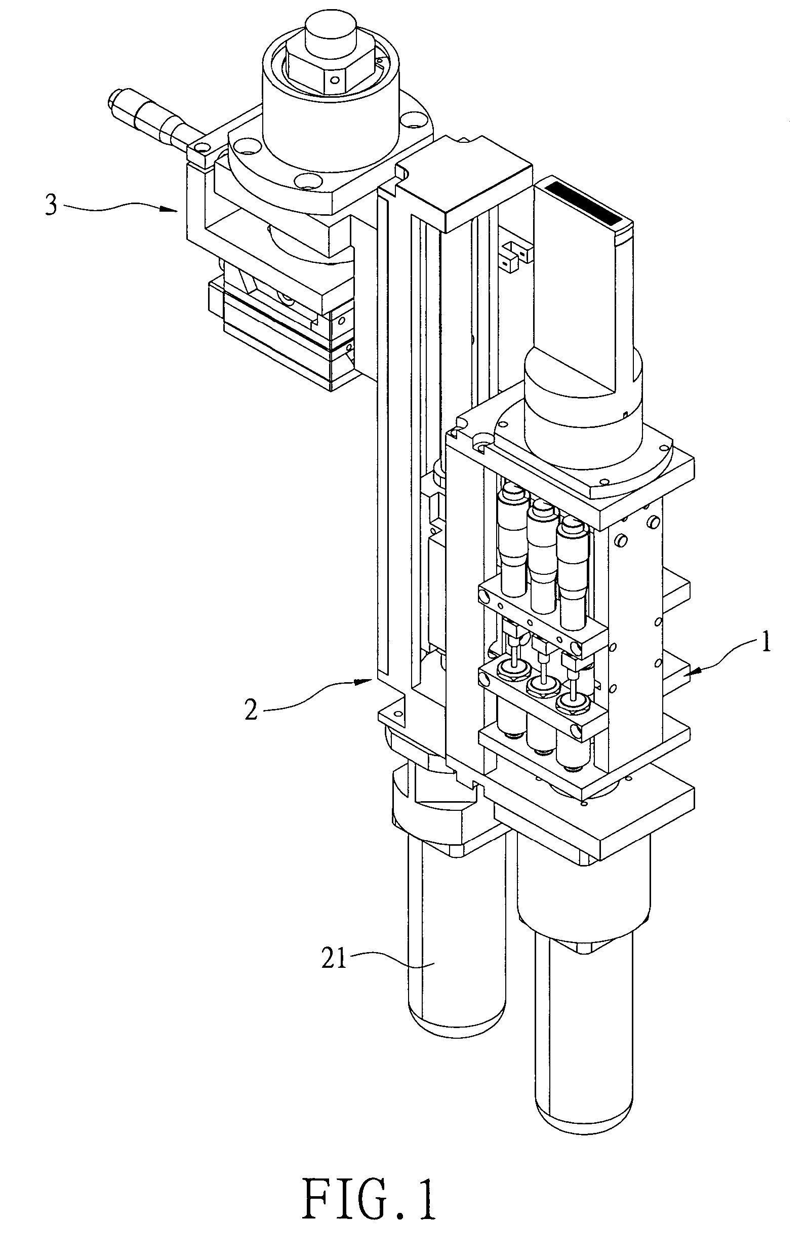
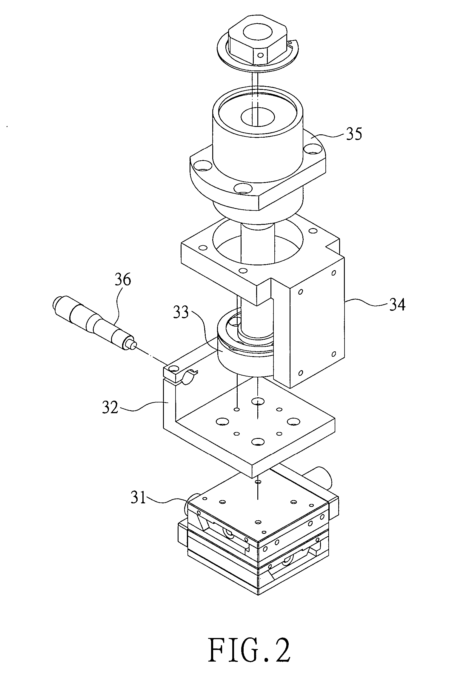
[0025] Regarding FIG. 1, an ejector with multi-ejection pins is disclosed to be used in the post-processes of the semiconductor industry, such as die sorting, die mounting, or similar processes, for lifting a plurality of dies outwards in order to separate them from adhesive film. The ejector includes a pin base 1, a pin-base vertical driver 2 connecting the pin base 1 and controlling the pin base 1 for ascent and descent, and a pin-base motion device 3 connecting the pin base 1 and controlling the pin base 1 to align the ejection pins 111 (in FIG. 11) with the respective dies. The pin-base motion device 3 is used to array and to position the ejection pins 111, in order to align with the respective dies. The pin base 1 is used to lift the ejection pins 111, and further suck the adhesive film onto a surface thereof. In addition, a predetermined quantity of ejection pins 111 is chosen individually according to the present invention. The pin-base vertical driver 2 equipped with a servo...


PUM

PropertyMeasurementUnit
Heightaaaaaaaaaa
Gravityaaaaaaaaaa

Abstract

An ejector with multi-ejection pins is used in the post-processes of the semiconductor industry and is used by a selection device to choose a predetermined quantity of ejection pins. When a propelling device lifts the selection device, a pin-base vertical driver controls the vertical motion of a pin base, and a pin-base motion device controls the planar motion of the pin base; the chosen ejection pins can be lifted to elevate the respective dies for separation from adhesive film.

Description

BACKGROUND OF THE INVENTION [0001] 1. Field of the Invention [0002] The present invention relates to an ejector with multi-ejection pins, and particularly relates to an ejector with multi-ejection pins for lifting a plurality of dies outwardly in order to them separate from adhesive film. [0003] 2. Background of the Invention [0004] IC (Integrated circuit) package assembly is the downstream supply of the IC industry. A wafer is separated from individual dies after the pre-processes are completed, and the dies are disposed on respective die pads arranged on a carrier adhesive tape for wrapping. The IC package assembly provides functions of environmental resistance, die support, electric conduction and further heat dissipation to increase an additional value of the IC product. [0005] Behind a fabricated wafer is an adhesive film (a so-called ‘blue adhesive film’) for die mounting. The blue adhesive film keeps the sawed wafer (individual dies) arranged regularly. During the die bonding...

Claims


Application Information

Patent Timeline
IPC IPC(8): B29C45/40
CPCH01L21/67092H01L21/67121H01L21/67132Y10S425/06
Inventor LU, WENG-JUNGHUANG, CHAO-HSIENHUANG, KUO-CHUNGLIN, HUNG-ICHANG, YING-FANG
Owner IND TECH RES INST
Learn More