Data relay device, data relay method and data transmission system

Inactive Publication Date: 2006-05-04
KK TOSHIBA
View PDF6 Cites 7 Cited by
  • Summary
  • Abstract
  • Description
  • Claims
  • Application Information

AI Technical Summary

Benefits of technology

[0014] Additional advantages of the invention will be set forth in the description which follows, and in part will be obvious from the description, or may be learned by practice of the invention. The objects and advantages of the invention may be realized and obtained by means of the instrumentalities and combinations particularly pointed out hereinafter.

Problems solved by technology

In this system configuration, up to now, in the case of the presence of difference in specifications between the AV data receiving equipment and the data relay device, since control data indicating a specification content of the receiving equipment is informed to the transmitting equipment via the relay device, the transmitting equipment transmits data in accordance with the specification of the receiving equipment, then, this system can not take advantage of specification of the relay device.
And the system doest take account of the problem in the case that there is a difference in specification between the relay device and the receiving equipment.
As mentioned above, up to this time, in the system configuration in which the data relay device is interposed between the data transmitting equipment and the data receiving equipment, when the specifications differ between the data receiving equipment and the data relay device, the control data indicating the specification content of the receiving equipment is notified to the transmission equipment through the relay device, so that there is the problem that the transmitting equipment transmits data in accordance with the specification of the receiving equipment and the system configuration can not take advantage of the specification of the relay device.

Method used


Image

  • Data relay device, data relay method and data transmission system
  • Data relay device, data relay method and data transmission system
  • Data relay device, data relay method and data transmission system

Examples


Embodiment Construction

[0019] Hereinafter, embodiments of the present invention will be described in detail by referring to the drawings.

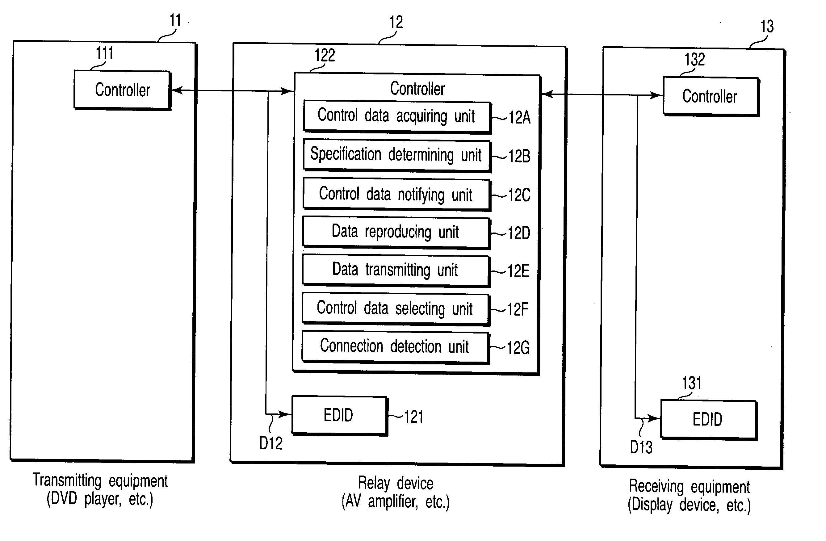
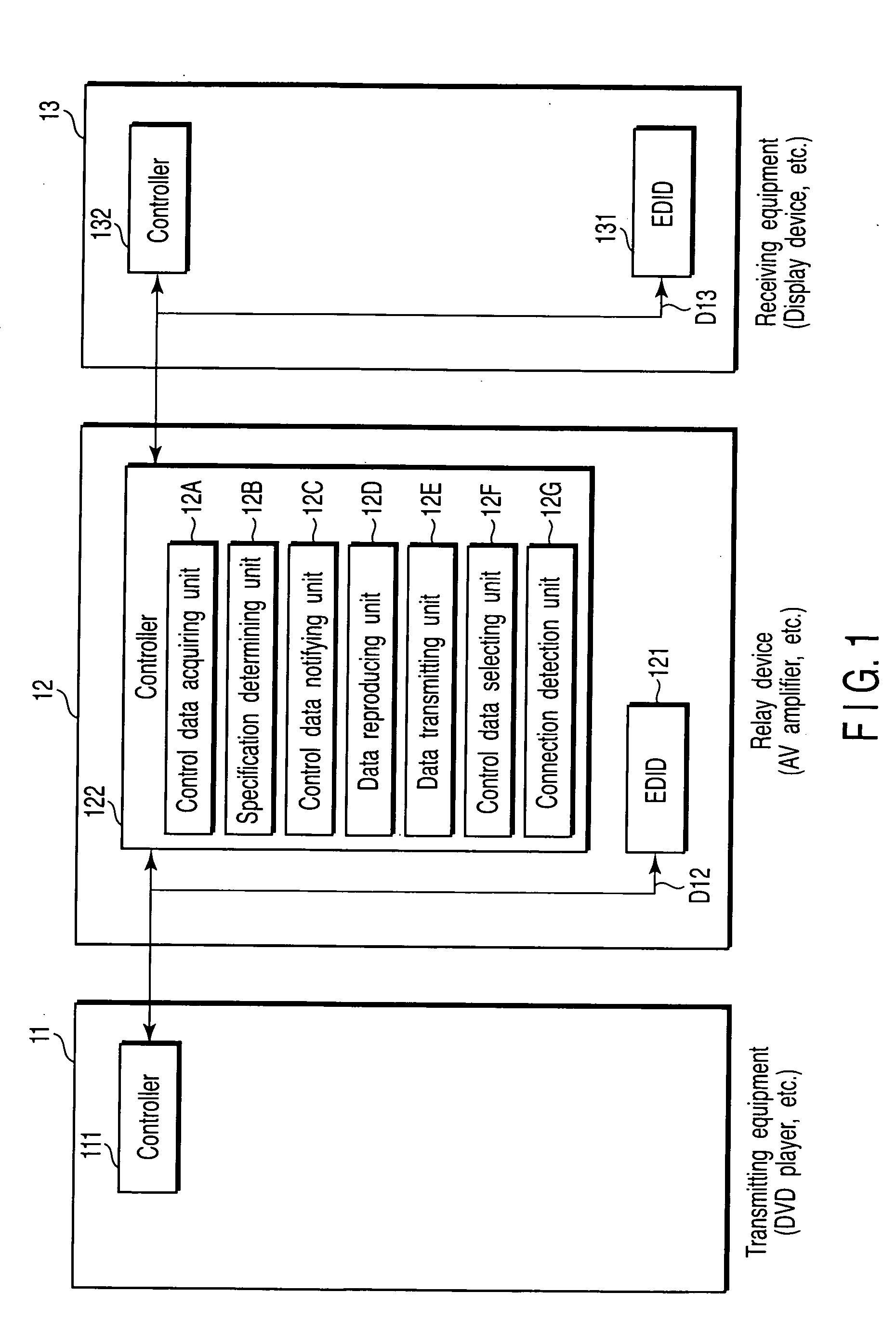
[0020]FIG. 1 is the block diagram showing the configuration of the AV data transmission system regarding the present invention. In FIG. 1, transmitting equipment (TX) 11 is, for example, a DVD player, a set-top box as a digital broadcasting tuner and the like. A relay device (RP) 12 is an AV amplifier, a video recording and reproducing device and the like for example. Receiving equipment (RX) 13 is a display device, a TV receiver, a video recording and reproducing device or the like for example.

[0021] Here, the TX 11, the RP 12 and the RX 13 compose a data transmission system corresponding to the HDMI with the HDCO adopted thereto. The RP 12 and the RX 13 have areas EDID 121 and EDID 131 holding control data D12 and D13 therein and controllers 122 and 132 controlling data held in the EDID 121 and EDID 131, respectively. The control data D12 and D13 held in the EDID 121...


PUM


Abstract

A relay device employs a control system which notifies control data indicating its own specification to transmitting equipment to receive data in a form matching to its own specification and acquires control data D13 from receiving equipment employing the control system and connected to a latter stage. The relay device determines whether its own specification is in a higher order or not in comparison a specification indicated by the control data D13 with its own specification, and if it is determined that its own specification is in the higher order, rewrites the control data D13 from the receiving equipment by its own control data D12 to notify it to the transmitting equipment. Thereby, the relay device can reproduce the data from the transmitting equipment in accordance with its own specification. At this time, since the relay device converts the received data from the transmitting equipment to transmit it, even the receiving equipment can reproduce it in accordance with an appropriate specification.

Description

CROSS-REFERENCE TO RELATED APPLICATIONS [0001] This application is based upon and claims the benefit of priority from prior Japanese Patent Application No. 2004-316816, filed Oct. 29, 2004, the entire contents of which are incorporated herein by reference. BACKGROUND OF THE INVENTION [0002] 1. Field of the Invention [0003] The present invention relates to a data relay device, a data relay method and a data transmission system using the device which is used for a data transmission system corresponding to a high-definition multimedia interface (HDMI) using, for example, high-bandwidth digital content protection (HDCP) and relays to output a data output from content [audio video (AV) data, etc.] transmitting equipment to content receiving equipment. [0004] 2. Description of the Related Art [0005] In recent years, the HDMI for a next-generation television has been standardized. This HDMI is a digital interface standard for the next-generation television with a function for a household e...

Claims


Application Information

Patent Timeline
IPC IPC(8): H03K11/00G06F13/00H04L29/06H04N5/44H04N7/173
CPCH04L12/2803H04L12/281H04L12/282H04L12/2832H04L2012/2849H04L69/08H04N21/647
Inventor UKAI, KAORUMUKAIDE, TAKANOBU
Owner KK TOSHIBA
Why Eureka
Try Eureka