
Using syslog and SNMP for scalable monitoring of networked devices

a networked device and monitoring system technology, applied in the direction of testing/monitoring control systems, program control, instruments, etc., can solve the problems of preventing the realization of this theory, wasting considerable time and energy of rf engineers, and developing low-cost rfid tags with acceptable performance levels

Inactive Publication Date: 2006-05-04
CISCO TECH INC
View PDF98 Cites 96 Cited by
  • Summary
  • Abstract
  • Description
  • Claims
  • Application Information

AI Technical Summary

Benefits of technology

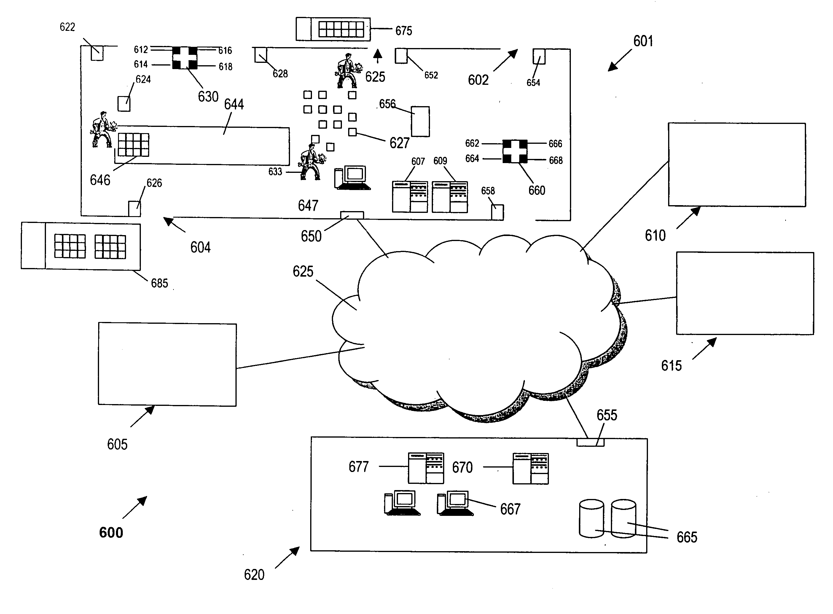
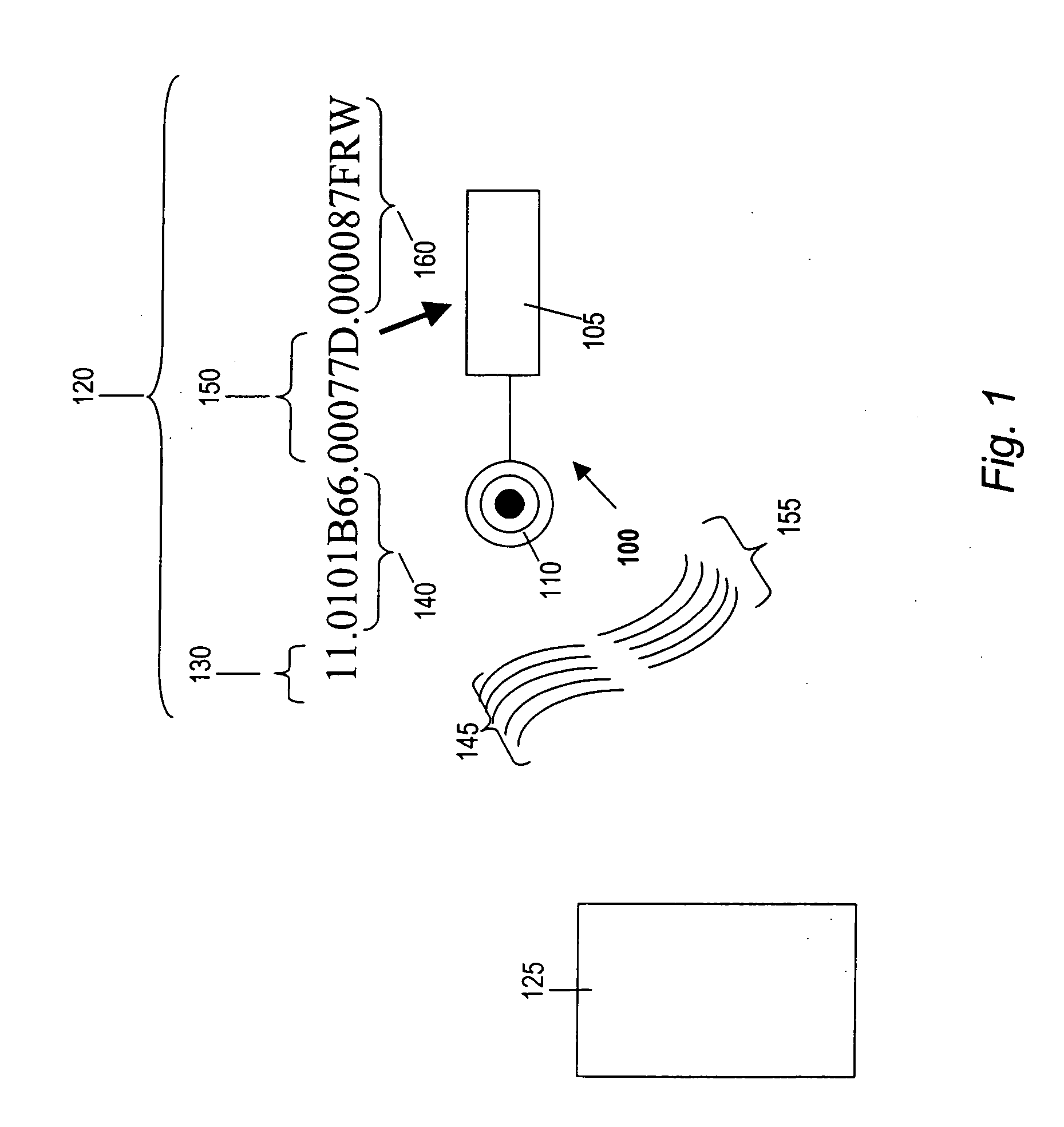
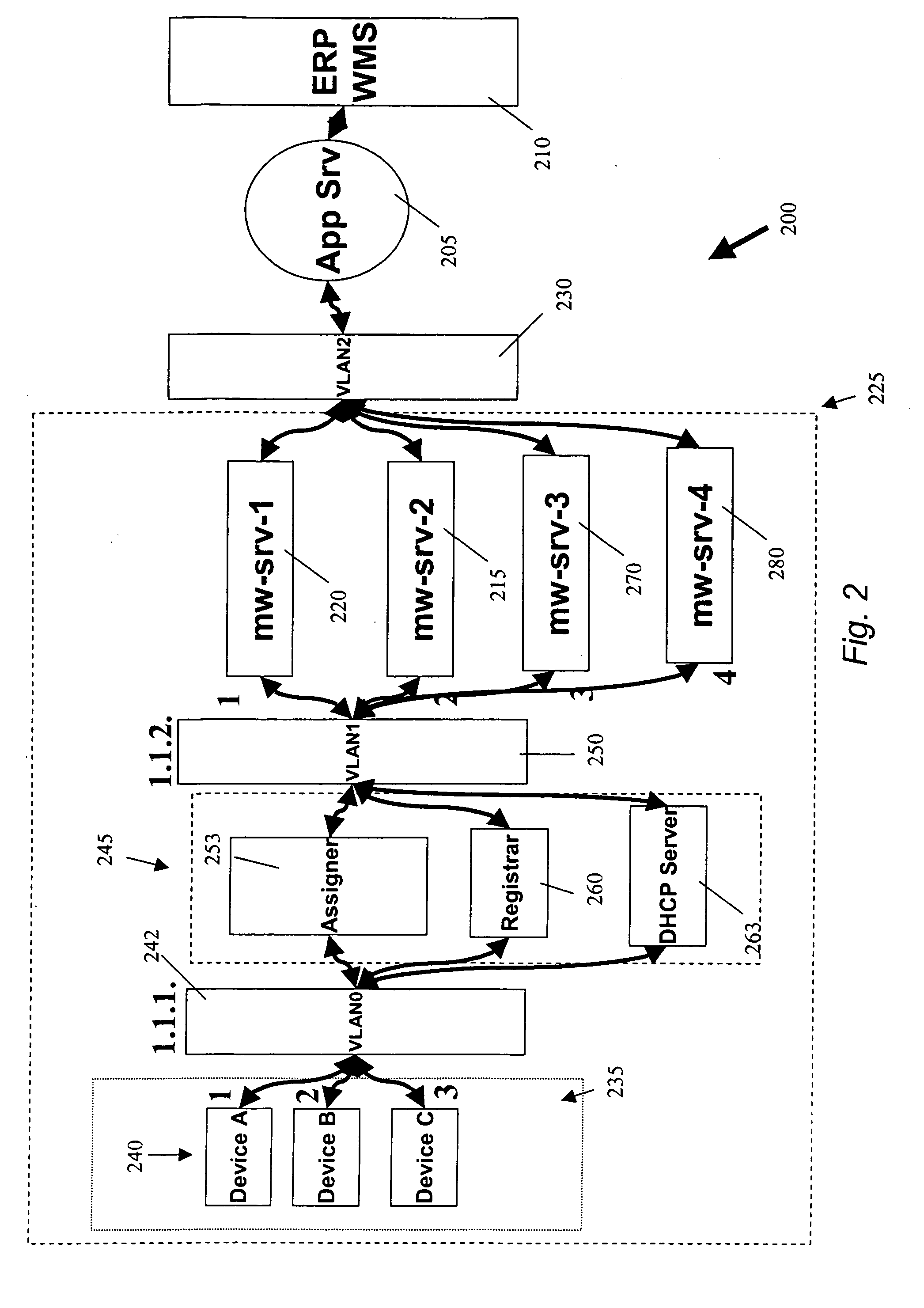
[0014] Methods and devices are provided for determining the status of a networked device, e.g., a networked RFID device. In some embodiments of the invention, one or more customized packets are used to transmit a message from networked devices to a server. The messag

Problems solved by technology

However, various difficulties have prevented this theory from being realized.
One problem that has required considerable time and energy from RF engineers is the development of lower-cost RFID tags with acceptable performance levels.
In part because of the significant efforts that have been expended in solving the foregoing problems, prior art systems and methods for networking RFID devices are rather primitive.
Prior art RFID devices and systems are not suitable for large-scale deployment of networks of RFID devices.
RFID devices do not currently achieve reliability levels required of customers.
Moreover, many RFID devices are deployed in a hostile industrial environment (such as a warehouse or factory) by relatively unskilled “IT” personnel.
However, when an RFID device is needed it must perform immediately or significant delays may ensue.
These delays may affect an entire supply chain and could result in significant costs.
In part because of the bandwidth consumed by the polling process, this is not a desirable method for networks involving large numbers of devices.
However, SNMP traps are not intended for routine status reporting.
Such use would be considered an abuse of SNMP and would not be well accepted by other standards bodies.

Method used


Image

  • Using syslog and SNMP for scalable monitoring of networked devices
  • Using syslog and SNMP for scalable monitoring of networked devices
  • Using syslog and SNMP for scalable monitoring of networked devices

Examples


Embodiment Construction

[0040] In this application, numerous specific details are set forth in order to provide a thorough understanding of the present invention. It will be obvious, however, to one skilled in the art, that the present invention may be practiced without some or all of these specific details. In other instances, well known process steps have not been described in detail in order not to obscure the present invention.

[0041] The present invention involves the management of networked devices, including not only the end devices (such as sensors, industrial devices and / or RFID devices) but also the switches, middleware servers, etc., that are in communication with such end devices. Although the present invention will be described primarily with reference to RFID networks, many aspects of the present invention can be applied to devices, including wireless and wired devices, in other types of networks. For example, the present invention may also be used for managing networked manufacturing devices...


PUM


Abstract

Methods and devices are provided for determining the status of a networked device. Messages from such devices may include information indicating the health, accuracy and / or reliability of a device and / or of the network that includes the device. Multiple message formats may be supported, e.g., heartbeat only, partial statistics, full statistics, etc. Transmission of such messages may be triggered by the occurrence of various conditions, such as the passage of a predetermined time interval, a predetermined change in one or more criteria, etc. In some implementations, a time-based message throttle establishes a minimum time interval between messages. Messages may be created in a format that is compatible with SNMP. Messages may be transmitted in more than one packet, if necessary. Messages may be sent to one or more devices, e.g., to one or more servers, according to various criteria.

Description

CROSS-REFERENCE TO RELATED APPLICATION [0001] This application is a continuation-in-part of U.S. patent application Ser. No. 10 / 891,238, entitled “Methods and Apparatus for Determining the Status of a Device” and filed on Jun. 13, 2004, which is hereby incorporated by reference in its entirety and for all purposes.BACKGROUND OF THE INVENTION [0002] 1. Field of the Invention [0003] The present invention relates methods and devices for monitoring the status of networked devices. More particularly, the present invention relates to monitoring the status of relatively unsophisticated devices, such as radio frequency identification (“RFID”) devices, in a network. [0004] 2. Description of the Related Art [0005]“Smart labels,” generally implemented by RFID tags, have been developed in an effort to address the shortcomings of bar codes and add greater functionality. RFID tags have been used to keep track of items such as airline baggage, items of clothing in a retail environment, cows and hi...

Claims


Application Information

Patent Timeline
IPC IPC(8): H04Q5/22
CPCG06K17/00H04Q5/22H04Q2213/13095H04Q2213/13389
Inventor HOWARTH, ARTHUR G.
Owner CISCO TECH INC
Learn More