Quality power from induction generator feeding variable speed motors

a variable speed motor and induction generator technology, applied in the direction of electric generator control, ac network to reduce harmonics/ripples, instruments, etc., can solve the problem of 8% distortion of the 200 kw generated at the utility interface, induction generators have an inherently lower power factor than, and synchronous generators are expensive and require additional controls. , to achieve the effect of improving heat recovery, producing quality power, and not degrading the quality of generated power

Inactive Publication Date: 2006-05-04
UNITED TECH CORP
View PDF12 Cites 4 Cited by
  • Summary
  • Abstract
  • Description
  • Claims
  • Application Information

AI Technical Summary

Benefits of technology

[0009] Objects of the invention include: producing quality power with a generator; producing quality electric power in a system having auxiliary variable speed motors associated with and powered by the generator, without degrading the quality of generated power which may be applied to a power utility grid; correction of power factor without the use of power factor correcting capacitors; producing well-shaped electric power with low harmonic distortion in a system employing an inexpensive induction generator associated with auxiliary variable speed motors; improved heat recovery; improved generation of electric power in an organic Rankin cycle heat recovery system; generating electrical power with low harmonic distortion, high power factor, and suitable anti-islanding in an organic Rankin cycle heat recovery system including variable speed induction motors as auxiliary equipment therein; and improved electric power generation having low harmonic distortion, high power factor and anti-islanding protection.

Problems solved by technology

Synchronous generators are expensive and require additional controls compared with other, cheaper generators such as induction generators, in which the rotor consists of simple conductive bars, short-circuited at the ends, which is much less expensive than synchronous generators.
However, induction generators have an inherently lower power factor than what is acceptable to utility grids.
This amounts to about 8% distortion of the 200 kW being generated at the utility interface.
The filter traps may result in the power factor to be more lagging.
Harmonic filter traps also increase the cost and space requirements of the installation where used.
This may be corrected by large power factor correcting capacitors 20, which increase the cost of the system, consume space, and are possible sources for self-excitation, all of which can be inappropriate in many installations.
These capacitors may require additional bulky series inductors for limiting harmonic current to the capacitors.

Method used


Image

  • Quality power from induction generator feeding variable speed motors
  • Quality power from induction generator feeding variable speed motors
  • Quality power from induction generator feeding variable speed motors

Examples


Embodiment Construction

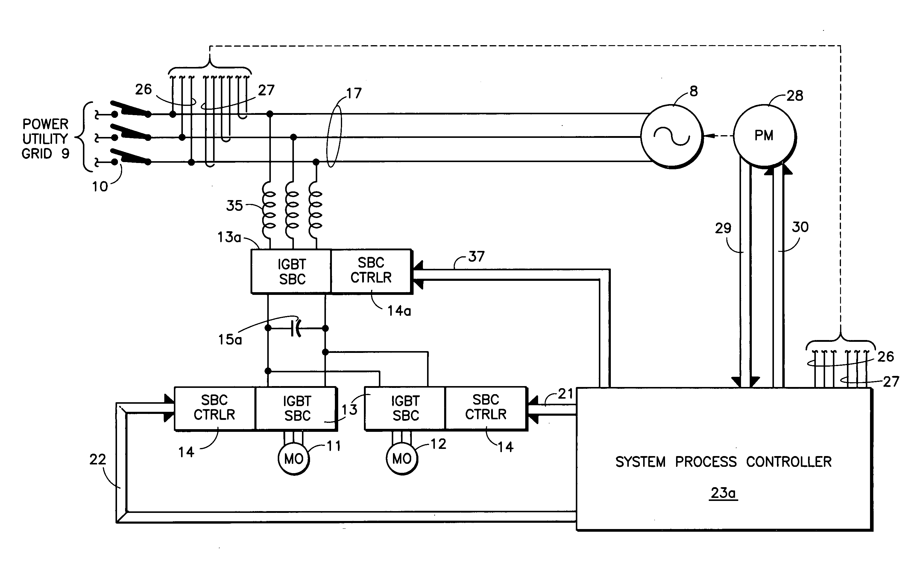
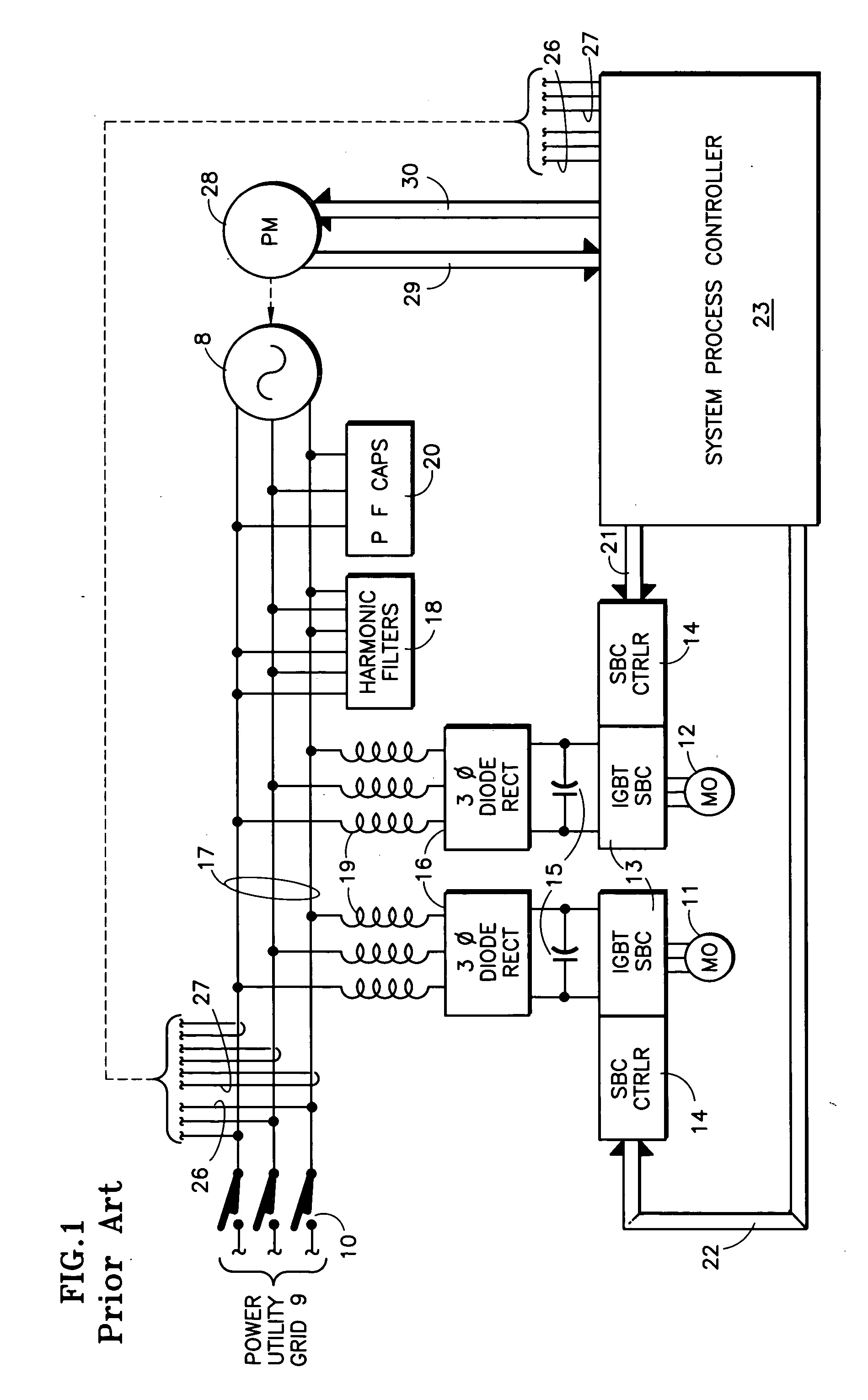
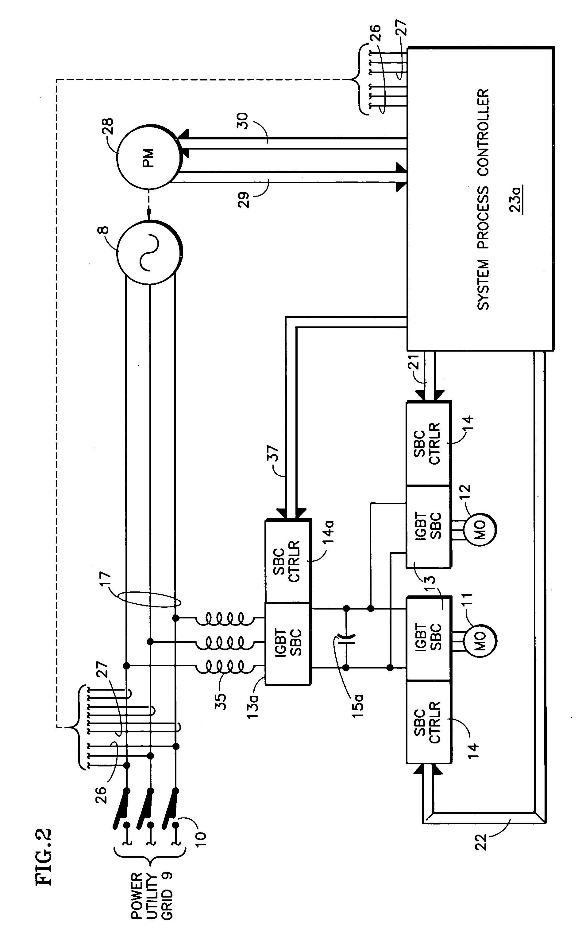
[0014] Referring to FIG. 1, one known system utilizes three-phase diode rectifiers 16 to provide the DC voltage 15 at the input to the IGBT converters 13. The converter controllers 14 respond to signals 21, 22 from a system process controller 23. The controller 23 responds to current and voltage signals 26, 27 indicative of the power generated by the electric power generator 8, including magnitude of power and power factor. The controller 23 also responds to signals 29 from whatever is the prime mover 28, and provides controlling signals 30 to the prime mover. The prime mover may, for instance, be a heat recovery device, such as an organic Rankin cycle heat recovery device.

[0015] The diode rectifiers draw current from the bus 17 in separated pulses of opposite phase, which equates to a highly distorted, semi-sine wave. Inductors 19 cause the current drawn by the rectifiers 16 to be more nearly sinusoidal, but not sufficiently to provide an acceptable waveshape on the bus 17 in orde...


PUM


Abstract

A prime mover (28) in a heat recovery system drives an induction generator (8) which feeds power to a utility grid (9) through a breaker (10) but also powers a load including auxiliary induction motors (11, 12). To provide acceptable waveform and power factor, the auxiliary equipment is driven through IGBT switched bridge converters (13) by DC voltage (15) generated by an IGBT switched bridge converter (13a), instead of three-phase diode rectifiers (16). The switched bridge converter controller (14a) is responsive to a system process controller (23a) which causes the switched bridge controller (13a) to be driven in response to the voltage (26) and current (27) on the generator bus (17). This eliminates the need for harmonic filters (18) and power factor capacitors (20) while improving the quality of the power generated. The controller (23a) trips the breaker if the voltage, frequency or power factor is out of limits.

Description

TECHNICAL FIELD [0001] This invention relates to providing power to a utility power grid from an induction generator which also provides power to variable speed motor drives associated therewith, such as in combined heat and power systems; the power factor and harmonics content (shape) of the power at the grid interface is controlled to be well within requirements for power provided to the utility, by actively controlling power in a manner to complement and compensate for undesirable harmonics and power factor. BACKGROUND ART [0002] It has become common for entities other than power utilities to generate electric power and to provide it to the utility grid, thereby to derive revenue or offset customer electric utility bills. Recapture and utilization of energy (such as heat) which would otherwise be wasted, as a byproduct of some useful function, is becoming commonplace. [0003] In some electric power generating systems, the manner of harnessing the energy that will operate the gener...

Claims


Application Information

Patent Timeline
Patent Type & Authority Applications(United States)
IPC IPC(8): H02P9/04F02D29/06
CPCH02J3/01Y02E40/40H02J3/1892H02P9/04
Inventor FREDETTE, STEVEN J.GROVER, RISHI
Owner UNITED TECH CORP
Why Eureka
Try Eureka