Fiber scope

a fiber and scope technology, applied in the field of image fibers, can solve the problems of reducing the contrast affecting and the size of the core of the pixels, so as to achieve the effect of not degrading the quality of the transmitted imag

Active Publication Date: 2007-04-12
FUJIKURA LTD
View PDF4 Cites 0 Cited by
  • Summary
  • Abstract
  • Description
  • Claims
  • Application Information

AI Technical Summary

Benefits of technology

[0010] In view of the above problems, an object of the present invention is to provide an image fiber in which a twisted portion is provided so that a transmitted image is rotated without degrading the quality of the transmitted image.

Problems solved by technology

When the twisted portion is formed through the twisting process at an excessively large rate of twist, i.e., when the degree of twisting is excessive, deformation such as bending, elongation, etc., of cores that form pixels tend to become too great, and problems may be encountered in that defects such as dark spots are included in the transmitted image because light cannot pass through the cores.
Another defect is that contrast in the transmitted image is reduced because light leaking from some cores affects adjacent cores.
In particular, the above-mentioned defects tend to be significant in the cores disposed near the periphery of the image fiber because deformation due to twisting is greater in the cores near the periphery than in the cores disposed around the center of the image fiber.
The above-mentioned defects may occur where the degree of twisting is locally significant in the twisted portion.

Method used


Image

  • Fiber scope
  • Fiber scope
  • Fiber scope

Examples


Embodiment Construction

[0024] The present invention will be explained below in detail.

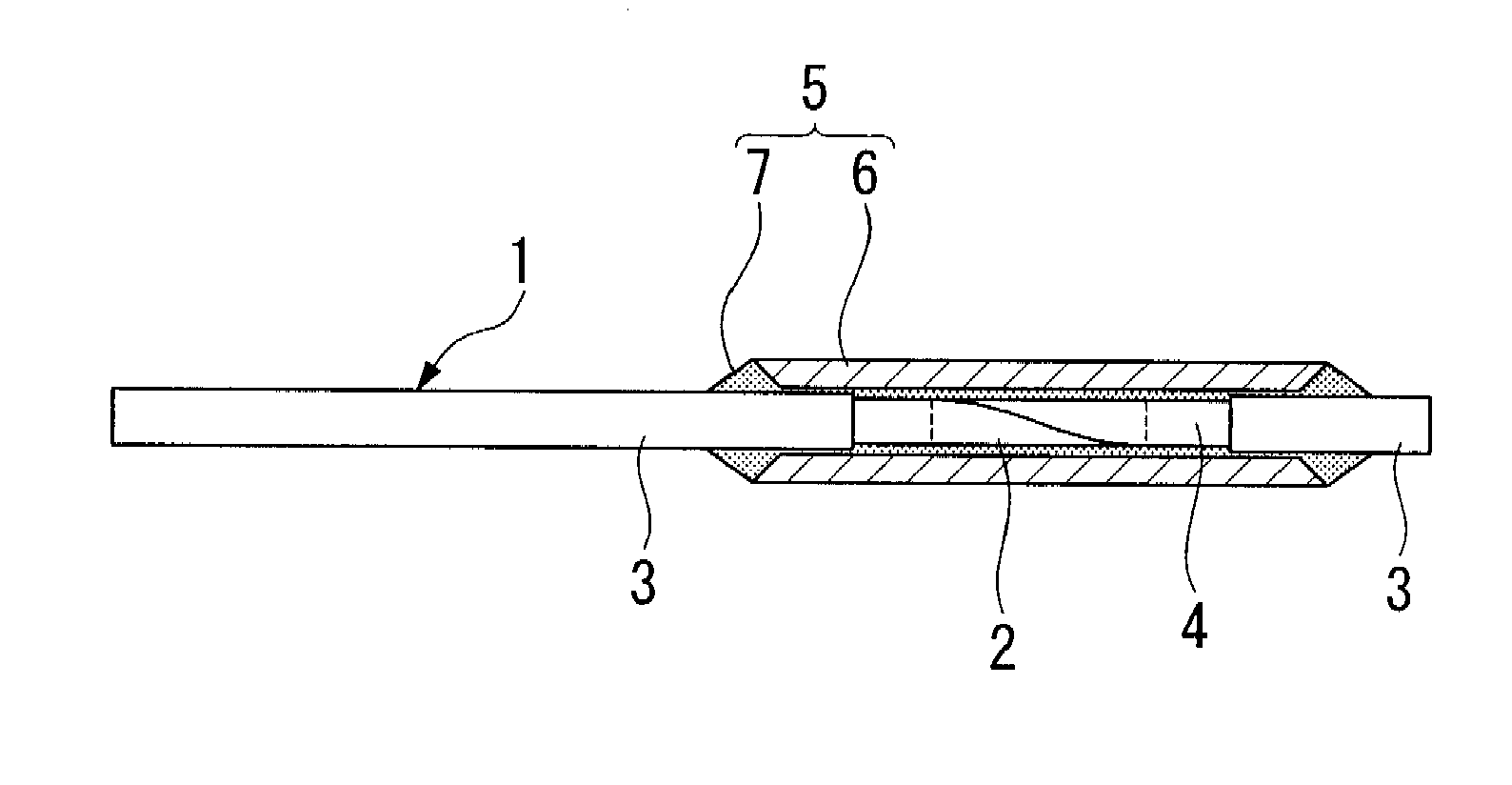
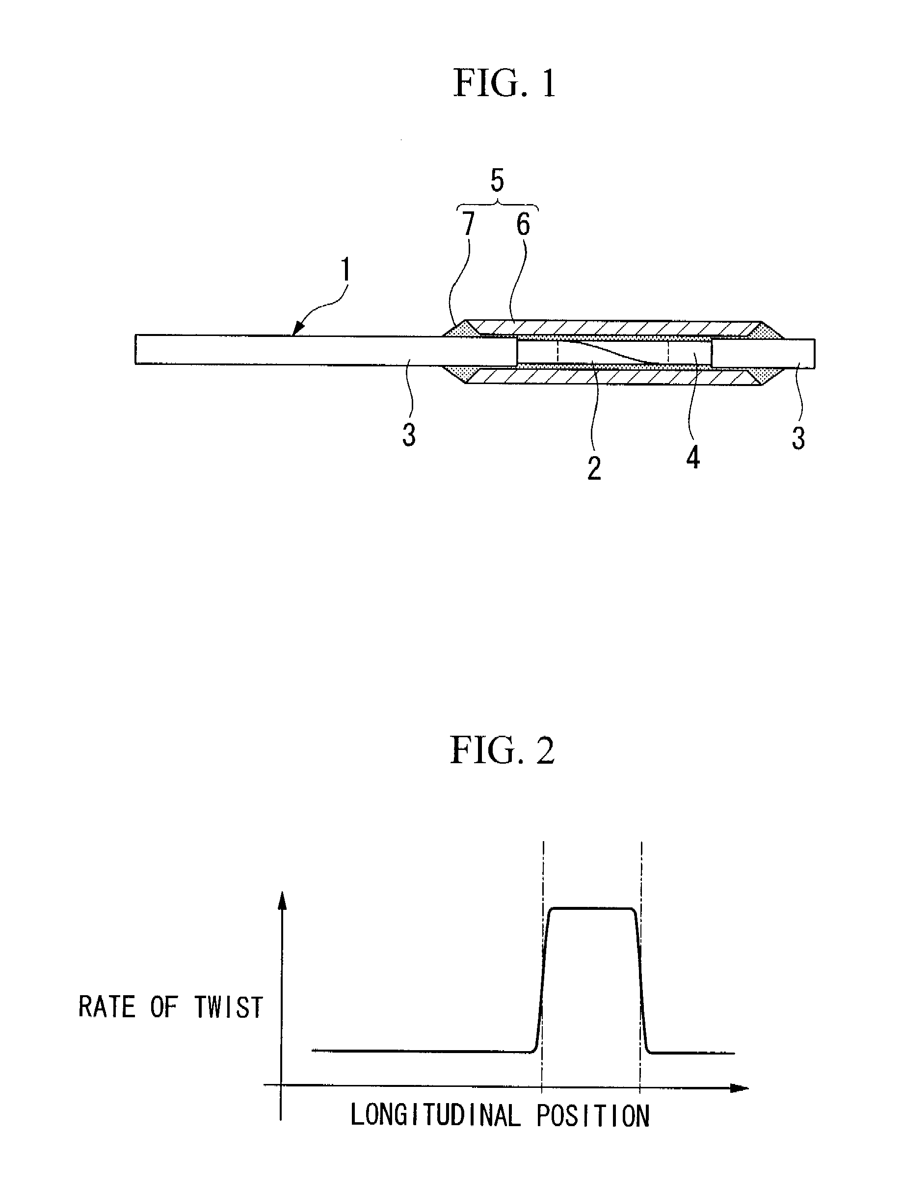
[0025]FIG. 1 shows an example of an image fiber, and reference numeral 1 indicates an image fiber. A twisted portion 2 is formed in the image fiber 1 along the longitudinal direction thereof.

[0026] The twisted portion 2 is formed by a process that includes: partially removing a protective layer 3 of the image fiber 1 to expose a portion of an image fiber body 4; heating the exposed portion of the image fiber body 4, except for a margin of a few millimeters from each end thereof, i.e., the middle portion of the exposed portion, using a heat source such as an oxyhydrogen flame burner to soften the image fiber body 4; twisting the image fiber body 4 in such a manner that an end of the image fiber 1 is fixed and the other end thereof is rotated about the center axis thereof, or both ends of the image fiber 1 are rotated about the center axis thereof in directions opposite to each other and cooling the image fiber body 4. D...


PUM

PropertyMeasurementUnit
refractive indexaaaaaaaaaa
lengthaaaaaaaaaa
lengthaaaaaaaaaa

Abstract

An image fiber includes an image fiber body having a twisted portion which is formed by heating, softening, and twisting a portion of the image fiber body. The rate of twist in the twisted portion is made to be constant. Moreover, the rate of twist may preferably be set in a range from 3.6° / mm to 3600° / mm. In addition, the rate of twist at the beginning portion of the twisted portion and the rate of twist at the end portion of the twisted portion may preferably be set in a range from 3.6° / mm to 360° / mm. The twisted portion may be provided with a protective element.

Description

[0001] This is a Divisional of application Ser. No. 10 / 648,275, filed Aug. 27, 2003. The entire disclosure of the prior application, application Ser. No. 10 / 648,275 is hereby incorporated by reference. [0002] Priority is claimed under 35 U.S.C. § 119 to Japanese Patent application No. 2002-249139, filed Aug. 28, 2002 which is incorporated herein by reference.BACKGROUND OF THE INVENTION [0003] 1. Field of the Invention [0004] The present invention relates to an image fiber in which a twisted portion is provided in order to rotate the orientation of a transmitted image, or to improve the quality of a transmitted image. [0005] 2. Background Art [0006] Image fibers, to which a twisting process is applied, are known in the art. One of the purposes of applying such a twisting process is to rotate the orientation of a transmitted image at the object side of an image fiber with respect to that at the observer's side thereof. Another purpose is to improve the quality of a transmitted image s...

Claims


Application Information

Patent Timeline
Patent Type & Authority Applications(United States)
IPC IPC(8): G02B6/06C03B37/15G02B6/28
CPCC03B37/15G02B6/06G02B6/2835Y02P40/57
Inventor NAKATATE, KENICHIKANEDA, KEIJITSUMANUMA, TAKASHI
Owner FUJIKURA LTD
Why Eureka
Try Eureka