
Heat exchanger support system and associated heat exchanger module

a technology of heat exchanger and support system, which is applied in the direction of stationary conduit assembly, stationary tubular conduit assembly, engine cooling apparatus, etc., can solve the problems of high cost increase fabrication cost, and introduce the risk of breakage of fixing or attachment elements, so as to achieve easy disassembly

Inactive Publication Date: 2006-05-04
LEVASSEUR ANTOINE +2
View PDF8 Cites 20 Cited by
  • Summary
  • Abstract
  • Description
  • Claims
  • Application Information

AI Technical Summary

Benefits of technology

[0009] Thanks to these features, the heat exchange components are easier to install and fix on the frame. Specifically, the means of fixing the heat exchange components are only on the frame itself. The components themselves, for example the heat exchangers, comprise no fixing means, in particular when they are not made of plastic. Consequently, they are easier to design and produce.
[0022] Thus, after a degree of deformation allowing the component to be attached, the force necessary to deform the fixing element increases considerably so that its plastic deformation and breakage are avoided.

Problems solved by technology

The stresses on these fixing elements are therefore high, introducing a risk of breakage of these fixing or attachment elements.
Each of the components of the heat exchange module must comprise fixing means such as lugs for fixing it to the cooling radiator, thereby increasing its fabrication cost.
Furthermore, the condenser of the air conditioning circuit and the motor-fan unit are fixed either side of the cooling radiator, which complicates the assembly of the heat exchange module because it is necessary to gain access to both faces of the radiator.
No air sealing is provided between the different heat exchangers of the module, such that a fraction of the air may escape through the space between the exchangers, which reduces the efficiency of the exchangers.

Method used


Image

  • Heat exchanger support system and associated heat exchanger module
  • Heat exchanger support system and associated heat exchanger module
  • Heat exchanger support system and associated heat exchanger module

Examples


Embodiment Construction

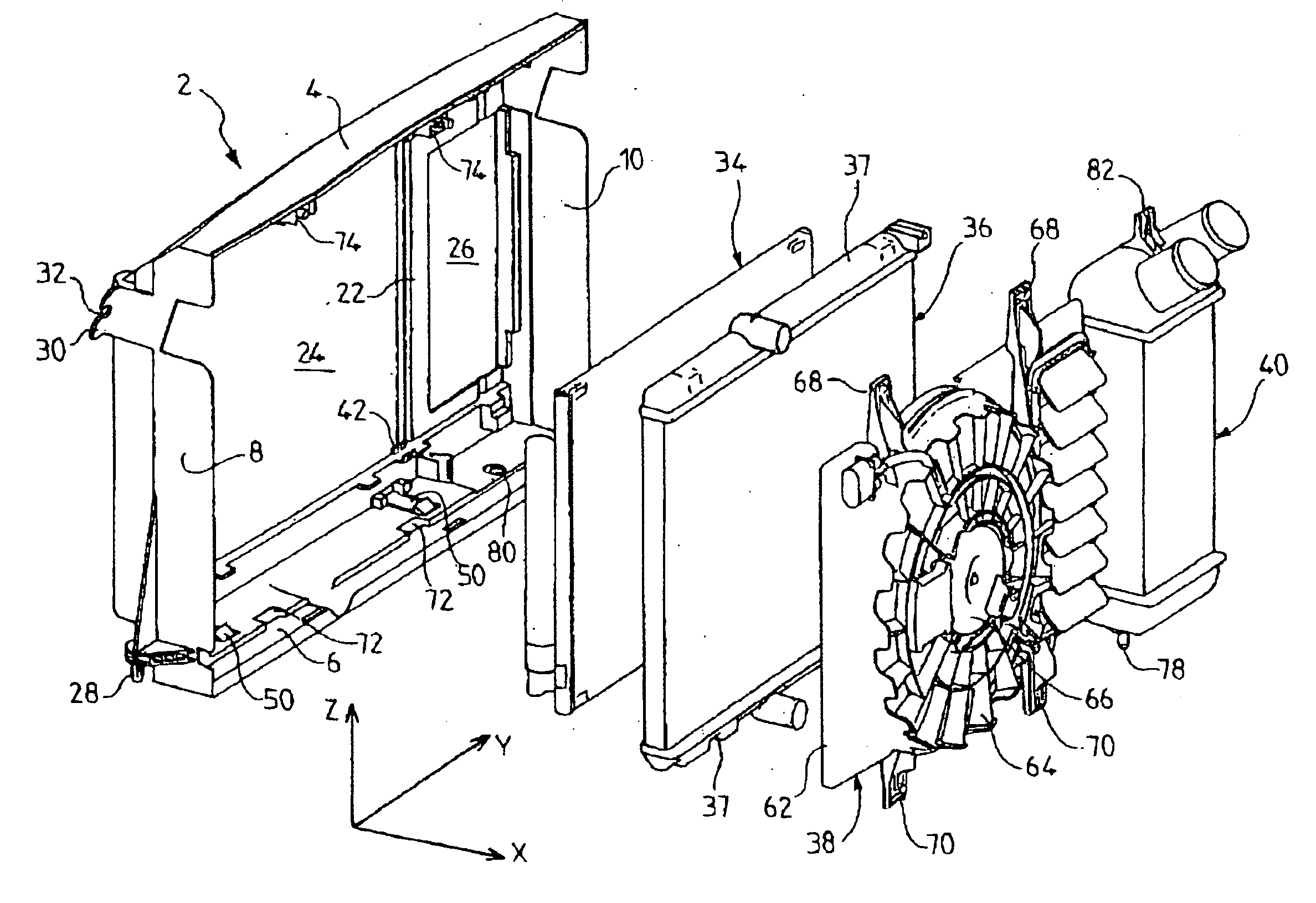
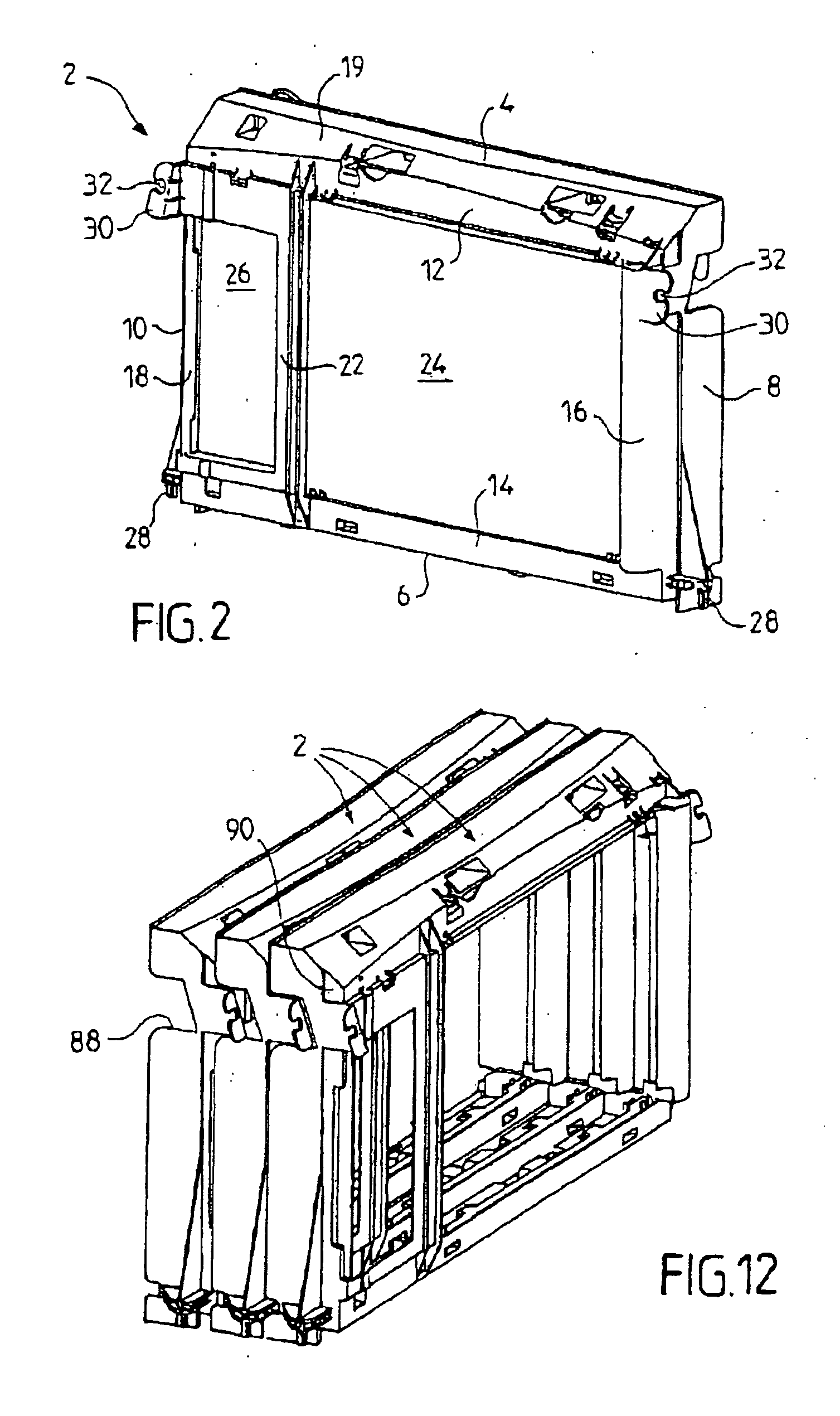
[0041]FIG. 1 shows an exploded view in perspective of a heat exchange module comprising a support frame 2 according to the present invention, and FIG. 2 shows a front view in perspective of this frame. The frame 2, rectangular in shape, comprises two long sides and two short sides. The top long side comprises a lateral horizontal face 4 and the bottom long side comprises a lateral horizontal face 6. The short sides comprise lateral vertical faces, 8 and 10 respectively. The long sides also comprise front faces, 12 and 14 respectively, while the short sides comprise front faces 16 and 18 respectively. Finally, the top long side of the frame comprises an inclined face 19 placed between the lateral horizontal face 4 and the front face 12. As can be seen more particularly in FIG. 3, which shows the frame in section, the horizontal face 10 comprises stiffening ribs 20.

[0042] The frame is divided into two portions by a vertical upright 22 which delimits a large opening 24 and a small ope...


PUM


Abstract

The heat exchanger support system (34, 36, 40) consists of a frame (2) comprising horizontal faces (4, 6) and vertical faces (8, 10) furnished with fixing means (42, 50, 72, 74, 80) for fixing heat exchange components such as a condenser (34), an engine cooling radiator (36), a motor-fan unit (38) and a supercharge air radiator (40). Each component is fixed directly to the frame (2) independently of the other components. The frame also comprises attachment elements (28, 30) allowing it to be mounted on a motor vehicle chassis via flexible vibration-damping means.

Description

[0001] The invention relates to heat exchangers, particularly for motor vehicles. BACKGROUND OF THE INVENTION [0002] Motor vehicles are fitted with several heat exchangers. In particular, they comprise at least one heat exchanger for cooling the motor vehicle engine. They also frequently comprise several other additional heat exchangers such as a condenser forming part of the air conditioning circuit for the passenger compartment of the vehicle or a supercharge air cooler. These heat exchangers are frequently put together to constitute an assembly of several exchangers called a heat exchange module. DESCRIPTION OF THE PRIOR ART [0003] In the prior art as currently known, the radiator for cooling the vehicle engine is mounted on the vehicle chassis, usually via flexible fixing elements, such as rubber blocks allowing the vibrations to be damped. The other components of the heat exchange module, such as the condenser or the supercharge air cooler are in turn mounted on the engine cool...

Claims


Application Information

Patent Timeline
IPC IPC(8): F28F9/00B60K11/04B60H1/32F01P3/18F28D1/04F28F9/26
CPCF28D1/0435F28F9/002F28F2275/085
Inventor LEVASSEUR, ANTOINEMARTINS, CARLOSBRISSON, SEBASTIEN
Owner LEVASSEUR ANTOINE
Learn More